Want to give your Arduino the ability to know exactly where it is on the planet? The NEO-6M GPS module can do just that—and more.
This tiny but powerful GPS module is perfect for all sorts of exciting projects like tracking vehicles, logging locations, or even sending a weather balloon on an adventure.
What makes the NEO-6M so special? It’s surprisingly easy to use, doesn’t drain much power, and won’t break the bank. That’s why it’s become a favorite among hobbyists and DIYers.
In this tutorial, we’ll guide you step-by-step through connecting the module to your Arduino, reading real-time GPS data, and understanding how it all works.
Ready to add location tracking to your Arduino project? Let’s dive in!
How does GPS work?
GPS (Global Positioning System) is a satellite-based navigation system that helps your phone or GPS device figure out exactly where you are on Earth.
There are at least 24 special satellites orbiting Earth in the GPS constellation. These satellites constantly broadcast radio signals down to Earth. Each signal contains two important pieces of information: the satellite’s exact position in space and the precise time when the signal was sent.
Your GPS device listens for these signals coming from the satellites. When your device receives a signal, it calculates how long it took that signal to travel from the satellite to your device. Since radio waves travel at the speed of light, your device can use that time to figure out how far away each satellite is.
Here’s where it gets interesting! By knowing its distance from at least three different satellites, your GPS device can pinpoint your location through a process called Trilateration. Think of it this way: each distance measurement creates an imaginary sphere around each satellite. Your location is the exact point where all these spheres intersect.

In real-world GPS systems, a fourth satellite is usually included for even better accuracy. This extra satellite helps correct any timing errors in your device’s internal clock. Even microsecond timing mistakes can throw off your position by hundreds of feet! With four satellites working together, your GPS can tell you not just where you are on a map (latitude and longitude), but also your altitude—how high above sea level you are.
Hardware Overview
NEO-6M GPS Chip
At the heart of the module is a GPS chip from U-blox, the NEO-6M.

This powerful chip can track up to 22 satellites and handle up to 50 tracking channels simultaneously. It achieves the industry’s highest level of tracking sensitivity (-161 dB), which means it can detect very weak satellite signals.
The chip offers decent performance, with different startup times depending on its state:
- Cold start (when it has no saved data): about 27 seconds to get your location
- Warm start (when it has some saved data): about 25 seconds
- Hot start (when it was recently used): just a second or so, which means it can quickly find your location again after a brief power-down
The module communicates with microcontrollers (like Arduino) using UART communication. It supports a wide range of communication speeds, from 4800 bps up to 230400 bps, with 9600 bps as the default.
Here are the specifications:
| Receiver Type | 50 channels, GPS L1(1575.42Mhz) |
| Horizontal Position Accuracy | 2.5m |
| Navigation Update Rate | 1HZ (5Hz maximum) |
| Capture Time | Cool start: 27sHot start: 1s |
| Navigation Sensitivity | -161dBm |
| Communication Protocol | NMEA, UBX Binary, RTCM |
| Serial Baud Rate | 4800-230400 (default 9600) |
| Operating Temperature | -40°C ~ 85°C |
| Operating Voltage | 2.7V ~ 3.6V |
| Operating Current | 45mA |
| TXD/RXD Impedance | 510Ω |
For more details, please refer to the datasheet below.
Position Fix LED Indicator
The module has a small LED that shows you the GPS status:
- No blinking: The module is still searching for satellites
- Blinking once every second: A position fix has been found (the module can see enough satellites to know your exact location)

Power Supply
The NEO-6M chip needs between 2.7 and 3.6 volts to operate. Fortunately, the module includes a MICREL MIC5205 Ultra-Low Dropout 3.3V regulator. Even better, the logic pins on the module are 5V-tolerant, which means you can connect it directly to an Arduino or any other 5V microcontroller without needing a level shifter.

The module uses about 45mA of current during normal operation. However, it also has a feature called Power Save Mode (PSM), which lets it turn off parts of the chip when they’re not needed. In PSM, it can use as little as 11mA, making it perfect for battery-powered devices like GPS watches or trackers.
Battery & EEPROM
The module includes a 4KB HK24C32 EEPROM chip and a small rechargeable button battery.

Together, they help save important information like real-time clock data, last known satellite positions, and configuration settings.
This saved information allows the module to perform a “hot start” on reboot. Without the battery, the GPS always has to do a “cold start,” which takes longer to find your location initially.
The battery charges by itself when the module is powered on and can keep the saved data for about two weeks even without power.
Antenna
To receive satellite signals, the module comes with a ceramic patch antenna.

You can easily attach this antenna to the small U.FL connector located on the module.

This antenna works well outdoors or in open skies. However, if you’re using the module in cities (urban canyons) or indoors, you might want to consider using a stronger external active GPS antenna instead.
NEO-6M GPS Module Pinout
The NEO-6M GPS module has four pins:

GND is the ground pin.
TxD (Transmitter) is the output from the GPS module that sends serial data (such as NMEA sentences). It should be connected to the RX (receive) pin of your microcontroller.
RxD (Receiver) is used to receive commands from the microcontroller. However, it is optional and not usually needed for basic GPS functions. If you want to use it, connect it to the TX (transmit) pin of your microcontroller.
VCC supplies power to the module. You can connect it directly to the 5V pin on your Arduino.
Wiring a NEO-6M GPS Module to an Arduino
Now that we understand how the NEO-6M GPS module works, let’s connect it to an Arduino.
First, check the module—it usually comes with unsoldered header pins. You’ll need to solder the pins before you can plug the module into a breadboard or connect it with jumper wires.
Next, make the power connections; Connect the VCC pin of the GPS module to the 5V pin and the GND pin to the GND pin on the Arduino.
As we’ve learned, the NEO-6M GPS module communicates using UART. On an Arduino UNO, you would normally connect UART devices to pins 0 and 1. However, there’s a problem – these same pins are also used when you connect your Arduino to your computer (like when uploading code or viewing messages in the serial monitor).
Since the Arduino Uno has only one built-in UART, we’ll need to create a second one specifically for our GPS module. Fortunately, there’s an easy solution! We can use the SoftwareSerial library. This library allows us to turn regular digital pins into extra UART communication pins.
For this project, we’ll use digital pins 2 and 3 on the Arduino. So connect the TxD pin of the GPS module to digital pin 2 and the RxD pin to digital pin 3 on the Arduino.
Finally, don’t forget to attach the ceramic patch antenna to the U.FL connector on the GPS module. You can carefully route the thin U.FL cable through one of the module’s mounting holes to help keep it secure.
The following table lists the pin connections:
| NEO-6M GPS Module | Arduino | |
| VCC | 5V | |
| GND | GND | |
| Tx | 2 | |
| Rx | 3 |

Once everything is connected, you’re all set and ready for programming!
Arduino Code – Reading GPS Data
One of the coolest things about the NEO-6M GPS receiver is that it begins sending location data as soon as it’s powered on. You don’t need to press any buttons or change any settings to make it work. The Arduino code below simply reads this data and sends it to the Serial Monitor so you can see what the GPS module is saying in real-time.
#include <SoftwareSerial.h>

// Choose two Arduino pins to use for software serial
int RXPin = 2;
int TXPin = 3;

// Create a software serial port called "gpsSerial"
SoftwareSerial gpsSerial(RXPin, TXPin);

void setup() {
  // Start the Arduino hardware serial port at 9600 baud
  Serial.begin(9600);

  // Start the software serial port at the GPS's default baud
  gpsSerial.begin(9600);
}

void loop() {
  // Displays information when a new sentence is available.
  while (gpsSerial.available() > 0)
    Serial.write(gpsSerial.read());
}
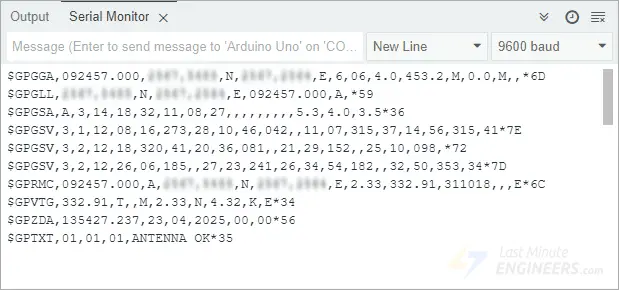
Once you upload the code to your Arduino, open the Serial Monitor. Make sure the baud rate is set to 9600. If everything is wired correctly and your module has a satellite lock, you’ll start seeing a stream of data on your screen. It might look a little strange at first—just lines of numbers and letters—but that’s actually standard GPS data in what’s called NMEA format, which we’ll learn more about later.
Code Explanation
At the very top of the code, we include the SoftwareSerial library. This is important because the regular serial pins on the Arduino (pins 0 and 1) are already used to talk to your computer. So, we need a second serial connection to talk to the GPS module. The SoftwareSerial library lets us use regular pins (like pins 2 and 3) to create this second connection.
#include <SoftwareSerial.h>We then choose two pins on the Arduino—pin 2 for receiving data and pin 3 for sending data—and create a new serial connection called gpsSerial.
// Choose two Arduino pins to use for software serial
int RXPin = 2;
int TXPin = 3;

// Create a software serial port called "gpsSerial"
SoftwareSerial gpsSerial(RXPin, TXPin);
In the setup() section, we set both the built-in serial port (used for the Serial Monitor) and our new GPS serial connection to a speed of 9600 baud, which is the default rate the GPS module uses to send information.
void setup() {
  // Start the Arduino hardware serial port at 9600 baud
  Serial.begin(9600);

  // Start the software serial port at the GPS's default baud
  gpsSerial.begin(9600);
}
Inside the loop() section, the code constantly checks if the GPS module has sent any new data. If it has, we immediately pass that data to the Serial Monitor. This setup doesn’t try to filter or decode the data—it just shows you exactly what the GPS module is sending.
void loop() {
  // Displays information when a new sentence is available.
  while (gpsSerial.available() > 0)
    Serial.write(gpsSerial.read());
}
NMEA Sentences
The data you see on the serial monitor from the GPS module comes in the form of NMEA sentences.
NMEA stands for National Marine Electronics Association. This organization created a standard way for GPS devices to communicate important information like GPS coordinates (latitude, longitude, altitude), speed, time, and satellite information.
The NMEA standard is formatted in lines of data called sentences. Each NMEA sentence has a specific structure:
- Each sentence starts with a dollar sign ($)
- Next comes an identifier that tells you what type of information follows (like $GPRMC or $GPGGA)
- The main part contains a list of values separated by commas
- At the end of the sentence, there’s often a checksum (marked with an asterisk *) that helps verify the data wasn’t corrupted.
Your GPS module sends these sentences at regular intervals called the update rate. The NEO-6M normally sends this information once every second (1Hz frequency). If you need more frequent updates, you can configure your module to send information up to five times per second (5Hz frequency).
Parsing NMEA Sentences
When we connect GPS modules to microcontrollers like Arduino boards, they need to “parse” the NMEA sentences. Parsing means breaking down the complicated sentence into useful pieces of information we can actually use.
There are many different types of NMEA sentences, but two of the most important ones are:
- $GPRMC: This sentence provides essential information like the time, date, position (latitude and longitude), course, and speed information.
- $GPGGA: This sentence provides important information about time, position, altitude, and fix-related data of the GPS receiver.
$GPRMC NMEA sentence
To better understand how NMEA messages are structured, let’s look at an example of the $GPRMC sentence:
$GPRMC, 123519, A, 4807.038, N, 01131.000, E,022.4, 084.4, 230394, 003.1, W*6A
| $ | Every NMEA sentence starts with $ character. |
| GPRMC | Global Positioning Recommended Minimum Coordinates |
| 123519 | Current time in UTC (hhmmss) – 12:35:19 UTC |
| A | Status: A = Active, V = Void |
| 4807.038 | Latitude 48 deg 07.038′ N |
| N | N/S Indicator: North |
| 01131.000 | Longitude 11 deg 31.000′ |
| E | E/W Indicator: East |
| 022.4 | Speed over the ground in knots |
| 084.4 | Track angle in degrees (true) |
| 230394 | Current Date – 23rd March 1994 (DDMMYY) |
| 003.1 | Magnetic Variation in degrees |
| W | Magnetic variation direction: West |
| *6A | Checksum (optional, used to verify data integrity) |
$GPGGA NMEA sentence
Now let’s look at a sample $GPGGA sentence:
$GPGGA, 123519, 4807.038, N, 01131.000, E, 1, 08, 0.9, 545.4, M, 46.9, M, , *47
| $ | Starting of NMEA sentence. |
| GPGGA | Global Positioning System Fix Data |
| 123519 | Current time in UTC (hhmmss) – 12:35:19 UTC |
| 4807.038 | Latitude 48 deg 07.038′ |
| N | N/S Indicator: North |
| 01131.000 | Longitude 11 deg 31.000′ |
| E | E/W Indicator: East |
| 1 | Fix Quality: 0 = Invalid, 1 = GPS fix, 2 = DGPS fix |
| 08 | Number of satellites in use |
| 0.9 | Horizontal dilution of precision (HDOP) |
| 545.4 | Altitude above mean sea level |
| M | Units of altitude (Meters) |
| 46.9 | Height of geoid above WGS84 ellipsoid |
| M | Units of geoid separation (Meters) |
| (empty field) | DGPS update time (if any) |
| (empty field) | DGPS reference station ID |
| *47 | Checksum (optional, used to verify data integrity) |
Beyond these basic sentences, there are many other NMEA sentence types that provide additional or specialized information. If you’re interested in learning more about other NMEA sentences, you can visit gpsinformation.org.
Library Installation
Even though NMEA sentences from the GPS module are written in a simple comma-separated format, parsing this data can be challenging and time-consuming. To make our job easier, we can use a library that takes care of all the heavy lifting. One of the most popular and reliable choices is the TinyGPSPlus library.
This library helps us extract useful information like location, date, time, altitude, speed, and direction from the GPS module with just a few simple commands.
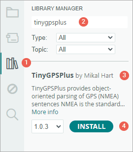
To install the library,
- First open your Arduino IDE program. Then click on the Library Manager icon on the left sidebar.
- Type “tinygpsplus” in the search box to filter your results.
- Look for the TinyGPSPlus library created by Mikal Hart.
- Click the Install button to add it to your Arduino IDE.
Arduino Code – Using the TinyGPSPlus Library
After installing the library, you can copy the sketch below into your Arduino IDE.
This test sketch reads information from the GPS module and displays your current location (latitude, longitude, and altitude) and the current UTC time (date and time) on the Serial Monitor. Go ahead and upload this sketch to your Arduino to see how it works before we explain it in detail.
#include <TinyGPSPlus.h>
#include <SoftwareSerial.h>

// Choose two Arduino pins to use for software serial
int RXPin = 2;
int TXPin = 3;

// Create a TinyGPSPlus object
TinyGPSPlus gps;

// Create a software serial port called "gpsSerial"
SoftwareSerial gpsSerial(RXPin, TXPin);

void setup() {
  // Start the Arduino hardware serial port at 9600 baud
  Serial.begin(9600);

  // Start the software serial port at the GPS's default baud
  gpsSerial.begin(9600);
}

void loop() {
  // This sketch displays information every time a new sentence is correctly encoded.
  while (gpsSerial.available() > 0)
    if (gps.encode(gpsSerial.read()))
      displayInfo();

  // If 5000 milliseconds pass and there are no characters coming in
  // over the software serial port, show a "No GPS detected" error
  if (millis() > 5000 && gps.charsProcessed() < 10) {
    Serial.println("No GPS detected");
    while (true)
      ;
  }
}

void displayInfo() {
  if (gps.location.isValid()) {
    Serial.print("Latitude: ");
    Serial.println(gps.location.lat(), 6);
    Serial.print("Longitude: ");
    Serial.println(gps.location.lng(), 6);
    Serial.print("Altitude: ");
    Serial.println(gps.altitude.meters());
  } else {
    Serial.println("Location: Not Available");
  }

  Serial.print("Date: ");
  if (gps.date.isValid()) {
    Serial.print(gps.date.month());
    Serial.print("/");
    Serial.print(gps.date.day());
    Serial.print("/");
    Serial.println(gps.date.year());
  } else {
    Serial.println("Not Available");
  }

  Serial.print("Time: ");
  if (gps.time.isValid()) {
    if (gps.time.hour() < 10) Serial.print(F("0"));
    Serial.print(gps.time.hour());
    Serial.print(":");
    if (gps.time.minute() < 10) Serial.print(F("0"));
    Serial.print(gps.time.minute());
    Serial.print(":");
    if (gps.time.second() < 10) Serial.print(F("0"));
    Serial.print(gps.time.second());
    Serial.print(".");
    if (gps.time.centisecond() < 10) Serial.print(F("0"));
    Serial.println(gps.time.centisecond());
  } else {
    Serial.println("Not Available");
  }

  Serial.println();
  Serial.println();
  delay(1000);
}
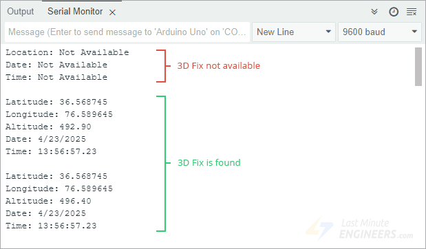
The output on the serial monitor looks like this:
Code Explanation
At the beginning of the code, we include two libraries: TinyGPSPlus and SoftwareSerial. We also specify which pins on the Arduino will be used to communicate with the GPS module. In this case, we’re using pin 2 to receive data (RX) and pin 3 to send data (TX).
#include <TinyGPSPlus.h>
#include <SoftwareSerial.h>

// Choose two Arduino pins to use for software serial
int RXPin = 2;
int TXPin = 3;
Next, we create an object named gps using the TinyGPSPlus library. This object gives us access to built-in functions that let us extract data like location, time, and more. Then we create a software serial connection named gpsSerial using the pins we selected earlier.
// Create a TinyGPSPlus object
TinyGPSPlus gps;

// Create a software serial port called "gpsSerial"
SoftwareSerial gpsSerial(RXPin, TXPin);
In the setup() section, we set both the built-in serial port (used for the Serial Monitor) and our new GPS serial connection to a speed of 9600 baud, which is the default rate the GPS module uses to send information.
void setup() {
  // Start the Arduino hardware serial port at 9600 baud
  Serial.begin(9600);

  // Start the software serial port at the GPS's default baud
  gpsSerial.begin(9600);
}
In the loop() function, we continuously check if the GPS module is sending any data. As soon as a complete line of data is received and properly decoded, we call a special function named displayInfo() to show all the useful information on your screen.
There’s also a safety check built in. If five seconds pass without receiving any data from the GPS, the Arduino prints “No GPS detected” to alert you that something might be wrong—such as a bad connection or the GPS hasn’t found enough satellites yet.
void loop() {
  // This sketch displays information every time a new sentence is correctly encoded.
  while (gpsSerial.available() > 0)
    if (gps.encode(gpsSerial.read()))
      displayInfo();

  // If 5000 milliseconds pass and there are no characters coming in
  // over the software serial port, show a "No GPS detected" error
  if (millis() > 5000 && gps.charsProcessed() < 10) {
    Serial.println("No GPS detected");
    while (true)
      ;
  }
}
The displayInfo() function checks if each piece of information from the GPS is valid before showing it on the Serial Monitor.
First, it checks if the location is valid. If it is, the function displays the latitude, longitude, and altitude. If not, it shows “Location: Not Available” to let you know that the GPS is still searching for satellites.
if (gps.location.isValid()) {
  Serial.print("Latitude: ");
  Serial.println(gps.location.lat(), 6);
  Serial.print("Longitude: ");
  Serial.println(gps.location.lng(), 6);
  Serial.print("Altitude: ");
  Serial.println(gps.altitude.meters());
} else {
  Serial.println("Location: Not Available");
}
Next, it checks the date. If the GPS has a valid date, it displays it in month/day/year format. If the date isn’t available yet, it shows “Not Available”.
Serial.print("Date: ");
if (gps.date.isValid()) {
  Serial.print(gps.date.month());
  Serial.print("/");
  Serial.print(gps.date.day());
  Serial.print("/");
  Serial.println(gps.date.year());
} else {
  Serial.println("Not Available");
}
Then it checks the time. If the GPS has a valid time, it displays the hour, minute, second, and centisecond in a clear, easy-to-read format. If the time hasn’t been received yet, you’ll see “Not Available” again.
Serial.print("Time: ");
if (gps.time.isValid()) {
  if (gps.time.hour() < 10) Serial.print(F("0"));
  Serial.print(gps.time.hour());
  Serial.print(":");
  if (gps.time.minute() < 10) Serial.print(F("0"));
  Serial.print(gps.time.minute());
  Serial.print(":");
  if (gps.time.second() < 10) Serial.print(F("0"));
  Serial.print(gps.time.second());
  Serial.print(".");
  if (gps.time.centisecond() < 10) Serial.print(F("0"));
  Serial.println(gps.time.centisecond());
} else {
  Serial.println("Not Available");
}
After showing all this information, the code includes a short pause before repeating the process, giving the Serial Monitor time to update with the new data.
Other Useful Functions in the TinyGPSPlus Library
The TinyGPSPlus library has many helpful functions that you can use with a TinyGPSPlus object to get different types of GPS data. Below are some of the most commonly used functions:
gps.speed.value(): This function gives you the current ground speed, measured in hundredths of a knot. For example, if it returns 1234, that means the speed is 12.34 knots.gps.course.value(): This function returns the current ground course, or the direction in which the device is moving. It’s also given in hundredths of a degree. So a value of 12345 would mean 123.45 degrees.gps.satellites.value(): This tells you how many satellites the GPS module can see and is using for location tracking. More satellites usually means more accurate positioning.gps.hdop.value(): This gives you the Horizontal Dilution of Precision (HDOP). It’s a number that shows how accurate your GPS location is. Lower numbers mean better accuracy.gps.age(): This function tells you how old the data is—how long it has been since the GPS module last updated the information. It gives the age in milliseconds. If the value is 1500 or more, it could mean the GPS has lost its signal (called a “lost fix”).
Custom Data Extraction
If you want to extract information that isn’t directly provided by the native TinyGPSPlus functions, the library also supports custom extraction.
Here’s how you can do it:
You tell the library which NMEA sentence you’re interested in, and which field number in that sentence you want to extract.
For example, if you want to get the magnetic variation (which shows the difference between true north and magnetic north), you can use this line of code:
TinyGPSCustom magneticVariation(gps, "GPRMC", 10);Then, to get the value, you use:
magneticVariation.value();U-center software
U-Center, developed by u-blox, is a powerful and free software tool used to evaluate, test performance, and configure u-blox GPS receivers, including the NEO-6M module. However, this software is available only for Windows computers.
U-Center provides both real-time structured data and graphical visualizations from your GPS receiver. Some of the main features include:
- Satellite Summary View – shows all visible satellites and signal strength
- Navigation Summary View – displays your current position, fix status, and more
- Compass, speedometer, clock, and altimeter – helpful instruments for location and movement tracking
- Chart View – lets you graph any two parameters of your choice
- Data Recording and Playback – allows you to save and review GPS data sessions
You can download the U-Center software from the official u-blox website.
Connecting NEO-6M to U-center
To use U-Center with the NEO-6M GPS module, you first need to connect the module to your PC using a USB to TTL converter.
The image below shows the NEO-6M connected to a PC using a PL2303 USB to TTL converter:

Using U-center
After you’ve successfully installed U-Center, you can open it by going to: Start Menu → All Programs → u-blox → u-center → u-center
Once the software starts, it will look something like this:
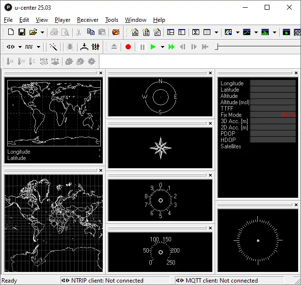
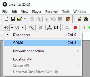
Next, locate the Communications Toolbar. Click the arrow next to the port icon to see a list of all available COM ports. Then, select the port where your GPS receiver is connected.
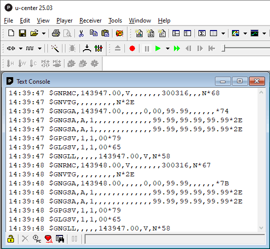
You can also click the Text Console button to view the raw NMEA sentences. This shows the actual ASCII data coming from the GPS module—very useful for quick inspections.
Another cool feature of U-Center is that it can show your GPS position on Google Maps, whether you’re online or offline.

For more detailed instructions and features, please refer to the official U-Center user guide on the u-blox website.
