
If you’re diving into the world of robotics, 3D printing, or building your own CNC machine, chances are you’ll soon come across stepper motors like the NEMA 17 or NEMA 23. These motors are popular because they offer precise, controlled movement—perfect for projects that need accurate positioning. But here’s the catch: these motors are power-hungry. They need much more electricity than an Arduino can safely supply on its own.
That’s where stepper motor drivers come in! And one of the most widely used and beginner-friendly options is the A4988 stepper motor driver. It’s compact, affordable, and capable of handling up to 2 amps per coil—enough power for most small to mid-sized stepper motors.
In this tutorial, we’ll walk you through how to hook up the A4988 driver to an Arduino, set the current limit to protect your motor, and we’ll explore several hands-on examples that will teach you how to control motor direction, speed, and even run multiple motors simultaneously.
Let’s get started and bring some motion to your next project!
A4988 Stepper Motor Driver Chip
At the heart of the module is a powerful microstepping driver chip made by Allegro—the A4988. Though small in size, this chip is packed with powerful features.

This driver can handle up to 35 volts and deliver 2 amps of electrical current. That’s enough power to run popular stepper motors like the NEMA 17 and NEMA 23.
One of the best features of the A4988 is that it includes a built-in “translator” that makes controlling stepper motors much easier. Normally, you would need to send complex electrical signals to four different wires in exactly the right order to make a stepper motor turn. The translator does all this complicated work for you. Instead, you only need to control two simple pins: one tells the motor to take a step, and the other tells it which direction to move. It’s that simple!
Another great feature is microstepping. This allows the motor to move more smoothly by breaking each full step into smaller pieces called microsteps. The A4988 offers five different microstep resolutions: full-step, half-step, quarter-step, eighth-step, and sixteenth-step.
For safety and reliability, the A4988 includes several safety features, such as under-voltage protection, short circuit protection, overcurrent protection, thermal shutdown, and shoot-through protection. These features help prevent damage to both the driver and your motor if something goes wrong.
Technical Specifications
Here are the specifications:
| Motor output voltage | 8V – 35V |
| Logic input voltage | 3V – 5.5V |
| Continuous current per phase | 1A |
| Maximum current per phase | 2A |
| Microstep resolution | full, 1/2, 1/4, 1/8 and 1/16 |
For more information, please refer to the datasheet below.
A4988 Motor Driver Pinout
The A4988 module has 16 pins in total, and each pin serves a specific purpose.

Let’s go over each group of pins to understand what they do and how they work.
Power Pins
The A4988 requires two separate power supplies:

VDD and GND pins supply power to the A4988’s internal logic circuitry. You can connect these to any voltage between 3V and 5.5V.
Whereas,
VMOT and GND pins provide power to the stepper motor itself. Depending on what type of motor you’re using, this voltage can range anywhere from 8V to 35V.
Warning:
This module uses low-ESR ceramic capacitors that, while efficient, make it vulnerable to destructive LC voltage spikes. These spikes can sometimes exceed 35V, which is more than the A4988 can handle, even if you’re only using a 12V power supply for your motor. When this happens, it can permanently destroy your driver module. To protect your driver from these dangerous spikes, you should always connect a large electrolytic capacitor (at least 47 µF) across motor power (VMOT) and ground, close to the driver.
Microstepping Pins
The A4988 driver offers five different options for step resolution: full-step, half-step, quarter-step, eighth-step, and sixteenth-step modes. Each mode divides the steps differently to give you various levels of precision.
The A4988 has three dedicated pins that let you choose which microstep resolution you want: MS1, MS2 and MS3.

By setting different logic levels (HIGH or LOW) on these pins, you can select any of the five available stepping modes:
| MS1 | MS2 | MS3 | Microstep Resolution |
| Low | Low | Low | Full step |
| High | Low | Low | Half step |
| Low | High | Low | Quarter step |
| High | High | Low | Eighth step |
| High | High | High | Sixteenth step |
It’s important to note that these pins have internal pull-down resistors that keep them LOW by default. This means that if you leave these pins unconnected, the motor will automatically operate in full-step mode.
Control Pins
The A4988 has two primary control inputs that manage motor operation: STEP and DIR.

STEP is the main control input for moving the motor. Every time you send a HIGH signal to this pin, the motor moves forward by one step. The frequency of these pulses determines the motor’s rotation speed—faster pulses result in faster rotation.
DIR pin controls which direction the motor spins. When you set this pin to HIGH, the motor rotates clockwise, and when you set it to LOW, the motor rotates counterclockwise. If your project only needs the motor to spin in one direction, you can simply connect this pin directly to VDD or GND.
Note that the STEP and DIR pins are not pulled to any particular voltage internally. This means you should never leave either of these pins disconnected (floating); always connect them to your microcontroller or pull them HIGH/LOW as needed.
Power State Control Pins
The A4988 has three input pins that control when and how the driver uses power: EN, RST, and SLP.

EN (Enable) pin enables or disables the A4988 driver. Since this is an active-low pin, pulling it LOW enables the driver, while pulling it HIGH disables the driver. The good news is that this pin is internally pulled LOW by default, which means the driver is enabled if it’s left unconnected. You might want to use this pin if you need an emergency stop button that can quickly shut down the motor for safety.
SLP (Sleep) pin puts the driver into a power-saving sleep mode. Like the EN pin, this is also active-low, meaning when you connect this pin to LOW, the driver goes to sleep and uses very little power. This feature is particularly useful for conserving power when the motor isn’t in use.
RST (Reset) pin is another active-low pin that resets the driver when pulled LOW, causing the motor to return to its starting position. Resetting is useful when you want to make sure the motor starts from the same place every time.
It’s important to note that the RST pin is floating. If you’re not planning to use the reset feature, you should connect the RST pin to the adjacent SLP pin. This will pull it high and keep the driver enabled.
Motor Output Pins
The motor output pins are where you actually connect your stepper motor to the driver.

You’ll typically find two pairs of wires on a bipolar stepper motor. The 1A and 1B pins connect to the first coil of your stepper motor, while the 2A and 2B pins connect to the second coil.
Wiring an A4988 Stepper Motor Driver to an Arduino
Let’s walk through how to connect an A4988 stepper motor driver to both a stepper motor and an Arduino.
The first step is giving your motor driver the power it needs to run your stepper motor. The A4988 requires two separate power supplies.
Step 1: Connect Motor Power
First, connect your motor power supply to the VMOT and GND pins on the A4988. This power should be between 8V and 35V, depending on your motor’s requirements.
Remember to place a large electrolytic capacitor (at least 47μF) across the VMOT and GND pins. This capacitor helps absorb sudden voltage spikes that could otherwise damage the driver.
Step 2: Connect Logic Power
Next, power the A4988’s internal logic circuitry. Connect the VDD and GND pins to the 5V and GND pins on your Arduino.
Step 3: Connect Control Input Pins
After that, connect the pins that actually control your motor’s movement: STEP and DIR. The STEP pin controls the movement of the motor, while the DIR pin controls which direction the motor spins. You can connect these pins to any of the Arduino’s digital output pins. For this example, let’s connect STEP to digital pin 3 and DIR to digital pin 2.
Step 4: Configure Microstepping
Now we have the three microstepping pins: MS1, MS2, and MS3. The A4988 driver has internal pull-down resistors on these pins, which means that if they are left unconnected, the driver defaults to full-step mode. For this example, we’ll leave them unconnected and use full-step mode.
Step 5: Handle SLP and RST Pins
There are two more pins you need to consider: SLP and RST. Both of these pins are active-low, meaning they must be pulled HIGH for the driver to remain enabled. The SLP pin is HIGH by default, but the RST pin is floating. So, connect the RST pin to the adjacent SLP pin to pull it HIGH and enable the board.
Step 6: Connect the Stepper Motor
Finally, connect your stepper motor to the driver’s output pins: 1A, 1B, 2A, and 2B. Connect one phase of the stepper motor to 1A and 1B, and the other phase to 2A and 2B.
Step 7: Find the Phases of Your Stepper Motor
Sometimes the trickiest part of connecting a stepper motor is figuring out which wires belong to the same phase. Here are two simple methods to identify them:
- The first method is to turn the motor shaft by hand—it should spin freely. Now, take two motor wires and briefly connect them together. While keeping those wires connected, try turning the shaft again. If the shaft suddenly becomes much harder to turn, you’ve found a phase. If nothing changes, try a different combination of wires.
- Another method is to use a multimeter in continuity mode. Touch the multimeter’s probes to two wires at a time. If the meter beeps or shows continuity, those wires belong to the same phase. If it stays silent, try a different pair.
Once you identify both pairs, connect one pair to 1A and 1B and the other to 2A and 2B—don’t worry about the order.

Cooling System – Heatsink
The A4988 driver chip has a maximum current rating of 2 A per coil, but in real-world use, the actual current you can deliver depends heavily on how well you can keep the chip cool. Without additional cooling, the A4988 can typically provide around 1 A per coil before it begins to overheat. To safely use higher currents—especially above 1 A—you’ll need to add a heatsink or implement another cooling method.
For this reason, A4988 driver modules often come with a small heatsink included in the package. It’s highly recommended that you install the heatsink before using the driver. When attaching the heatsink, be careful to ensure it doesn’t make contact with any nearby pins or other electronic components on the board.

Current limiting
One way to maximize stepper motor performance is to supply it with a higher voltage than it’s officially rated for. In particular, using a higher voltage generally allows for higher step rates and increased stepping torque.
Let’s take an example to understand this better. Suppose you’re using a stepper motor that has a maximum current rating of 1 A and a coil resistance of 5 Ω. This indicates a maximum motor supply of 5 V (1 A × 5 Ω = 5 V). Using such a motor with 12 V would allow higher step rates, but the problem is, if you just connect 12 V directly, the motor will try to pull too much current—well beyond the safe 1 A limit. When this happens, the coils inside the motor can overheat, which can permanently damage the motor.
In order to safely use a voltage higher than the motor’s rated voltage, you need to limit the current flowing through the motor’s coils. That’s exactly why the A4988 stepper motor driver includes a small current limit potentiometer. This allows you to set the maximum current that flows through the motor’s coils.

By adjusting the potentiometer properly, you make sure the motor never draws more current than it can safely handle, which helps prevent overheating and keeps your motor safe.
There are two main ways to adjust the current limit on the A4988:
Method 1:
In this method, you put the driver into full-step mode and use a multimeter to directly measure the current flowing through one of the coils while adjusting the current limit potentiometer.
- First, check the datasheet for your stepper motor to find its rated current. For example, let’s say you’re using a NEMA 17 stepper motor with 200 steps per revolution, rated at 1.5A per coil.
- Wire your motor and driver as explained in the earlier section. However, instead of connecting the STEP and DIR pins to your Arduino’s digital pins, connect both directly to the 5V pin on your Arduino. This keeps your motor energized and holding a fixed position.
- Make sure to disconnect the three microstepping pins to set the driver to full-step mode.
- Next, place your ammeter (or multimeter in current mode) in series with one of the motor coils so that the current flows from your meter to the motor coil. To do this, disconnect one wire from either the 1A or 1B terminal on your driver. Connect one probe of your ammeter to that terminal, and connect the other probe to the loose motor wire.
- With everything connected and powered up, you should see a current reading on your multimeter. Now carefully turn the current limit potentiometer with a small screwdriver while watching the reading on your meter. Adjust it until the current matches your motor’s rated value—in this case, 1.5A.
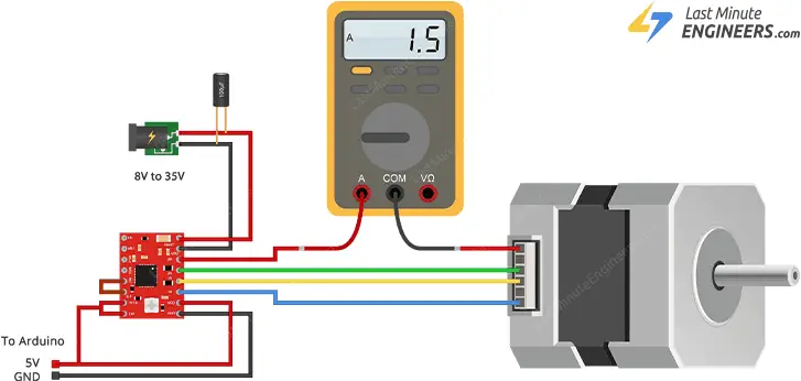
Note that the current you are measuring is only 70% of the actual current limit setting, since both coils are always on and limited to this value in full-step mode, so if you later enable microstepping modes, the current through the coils will be able to exceed this measured full-step current by 40% (1/0.7) on certain steps; please take this into account when using this method to set the current limit.
Method 2:
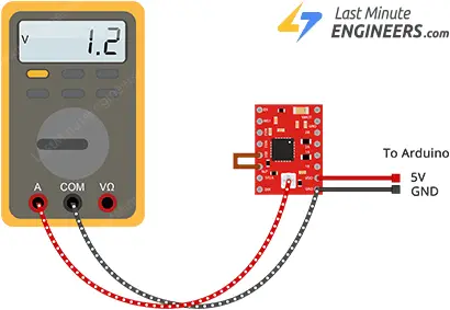
A more common method—especially for beginners—is to adjust the reference voltage, or Vref, on the driver. This method works even when the motor isn’t hooked up or powered.
- Start by checking your stepper motor’s datasheet to find its rated current. For example, let’s say you’re using a NEMA 17 stepper motor with 200 steps per revolution, rated at 1.5A per coil.
- Wire your motor and driver as explained in the earlier section. However, for this method, you don’t need to connect your motor because you’re only working with the driver. So, it’s safe to disconnect both the motor and the motor power supply. Also, make sure to disconnect the STEP and DIR pins, since they won’t be used in this method.
- Now locate the current sense resistors. Look closely at your A4988 driver board and find the tiny SMD resistors located near the main driver chip.
- These resistors will have a code printed on top of them – something like “R050,” “R100,” or “R200.” This code tells you the resistance value: R050 means 0.05 ohms, R100 means 0.1 ohms, and R200 means 0.2 ohms. Different manufacturers use different values, so you need to check your specific board. In our example, let’s say you find “R100” printed on the resistors, which means they’re 0.1 ohms each.
- Calculate the reference voltage using this formula:
Vref = I_limit × 8 × R_s
Where:
I_limit is your motor’s maximum current per coil (in amps)
R_s is the value of the current sense resistors (in ohms)
Using our NEMA 17 example with 1.5A current rating and 0.1-ohm sense resistors: Vref = 1.5 × 8 × 0.1 = 1.2 volts This means you need to adjust the potentiometer until the reference voltage reads exactly 1.2 volts.
- Set your multimeter to measure DC voltage. Touch the black probe to any ground point on the driver board, and carefully touch the red probe to the metal top of the current limit potentiometer. This small metal screw head actually serves as a test point that gives you the reference voltage. While watching your multimeter reading, slowly turn the potentiometer with a small screwdriver. Adjust carefully until you reach your calculated target voltage—in our example, 1.2 volts.
Let’s work through a few more examples to make sure you understand how to apply these concepts to different motors.
- Example 1: If you want to be more conservative and limit your 1.5A motor to only 1A for cooler operation and longer motor life, you would set: Vref = 1.0 × 8 × 0.1 = 0.8 volts
- Example 2: If you have a smaller stepper motor rated for 0.8A per coil and R050 (0.05-ohm) sense resistors, you would set: Vref = 0.8 × 8 × 0.05 = 0.32 volts
- Example 3: If you have a larger motor rated for 2.0A per coil with R200 (0.2-ohm) sense resistors, you would set: Vref = 2.0 × 8 × 0.2 = 3.2 volts
You can make this adjustment quickly and easily by connecting one end of the alligator clip test lead to the shank of a metal screwdriver and the other end to your multimeter. This allows you to measure the voltage while making the adjustment.
We tried both methods for setting the current limit on the A4988 driver, and they gave us roughly the same results.
No matter which method you use, just remember that the main goal of setting a current limit is to protect your stepper motor. Running a motor with too much current might give you more torque in the short term, but it also causes the motor to heat up more, which can shorten the motor’s lifespan. On the other hand, if you set the current too low, the motor won’t get damaged, but it may not have enough power to perform its task properly. The key is to find that sweet spot where your motor has enough power to perform its tasks while staying cool and lasting a long time.
Arduino Example Code 1 – Without a Library
In this example, we’ll learn how to control the speed and direction of a bipolar stepper motor using the A4988 driver and an Arduino, without using any library. This simple sketch helps you see exactly how the control signals affect motor behavior.
// Define pin connections & motor's steps per revolution
const int dirPin = 2;
const int stepPin = 3;
const int stepsPerRevolution = 200;

void setup() {
  // Declare pins as Outputs
  pinMode(stepPin, OUTPUT);
  pinMode(dirPin, OUTPUT);
}

void loop() {
  // Set motor direction clockwise
  digitalWrite(dirPin, HIGH);

  // Spin motor slowly
  for (int x = 0; x < stepsPerRevolution; x++) {
    digitalWrite(stepPin, HIGH);
    delayMicroseconds(2000);
    digitalWrite(stepPin, LOW);
    delayMicroseconds(2000);
  }
  delay(1000);  // Wait a second

  // Set motor direction counterclockwise
  digitalWrite(dirPin, LOW);

  // Spin motor quickly
  for (int x = 0; x < stepsPerRevolution; x++) {
    digitalWrite(stepPin, HIGH);
    delayMicroseconds(1000);
    digitalWrite(stepPin, LOW);
    delayMicroseconds(1000);
  }
  delay(1000);  // Wait a second
}
Code Explanation:
The sketch starts by defining the Arduino pins that connect to the A4988’s STEP and DIR pins.
const int dirPin = 2;
const int stepPin = 3;
We also define a variable to store the number of steps the motor needs to make one complete rotation. In our case, that’s 200 steps per revolution, which is standard for most NEMA 17 stepper motors. If your motor has a different number of steps per revolution, simply adjust this value accordingly.
const int stepsPerRevolution = 200;In the setup() section, we set both the STEP and DIR pins as outputs so the Arduino can send signals through them.
pinMode(stepPin, OUTPUT);
pinMode(dirPin, OUTPUT);
In the loop() section, we first make the motor rotate clockwise at a slow speed. To do this, we set the DIR pin to HIGH, which tells the motor to turn clockwise. Then we run a loop that sends 200 pulses to the STEP pin—one pulse for each step of the motor. Between each pulse, we wait 2000 microseconds (or 2 milliseconds), which makes the motor spin slowly.
// Set motor direction clockwise
digitalWrite(dirPin, HIGH);

// Spin motor slowly
for (int x = 0; x < stepsPerRevolution; x++) {
  digitalWrite(stepPin, HIGH);
  delayMicroseconds(2000);
  digitalWrite(stepPin, LOW);
  delayMicroseconds(2000);
}
delay(1000);  // Wait a second
After completing the first rotation, we pause for one second. Then, we change the direction by setting the DIR pin to LOW, which makes the motor turn counterclockwise. We send the same 200 pulses to the STEP pin again, but this time we reduce the delay between pulses to 1000 microseconds. This shorter delay makes the motor spin twice as fast in the opposite direction. After another one-second pause, the whole loop starts again.
// Set motor direction counterclockwise
digitalWrite(dirPin, LOW);

// Spin motor quickly
for (int x = 0; x < stepsPerRevolution; x++) {
  digitalWrite(stepPin, HIGH);
  delayMicroseconds(1000);
  digitalWrite(stepPin, LOW);
  delayMicroseconds(1000);
}
delay(1000);  // Wait a second
The key to controlling motor speed lies in adjusting the delay between the HIGH and LOW signals sent to the STEP pin. A shorter delay makes the motor turn faster, while a longer delay makes it turn slower.
Arduino Example Code 2 – Using AccelStepper library
The earlier sketch works fine for simple projects with a single motor. However, if you need to control multiple stepper motors simultaneously, or if you want smoother movement with acceleration and deceleration, you’ll need something more advanced.
That’s where the AccelStepper library comes in! This powerful library is specifically designed for more sophisticated stepper motor control.
Since this library doesn’t come pre-installed with Arduino IDE, you’ll need to install it before using it.
Library Installation
To install the library,
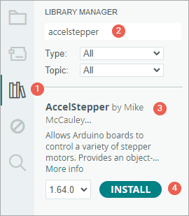
- First open your Arduino IDE program. Then click on the Library Manager icon on the left sidebar.
- Type “accelstepper” in the search box to filter your results.
- Look for the AccelStepper library by Mike McCauley.
- Click the Install button to add it to your Arduino IDE.
Arduino Code
Here is a simple sketch that makes the motor accelerate in one direction and then decelerate until it stops completely. After completing one full rotation, the motor will reverse direction and repeat the process.
// Include the AccelStepper Library
#include <AccelStepper.h>

// Define pin connections
const int dirPin = 2;
const int stepPin = 3;

// Define motor interface type
#define motorInterfaceType 1

// Creates an instance
AccelStepper myStepper(motorInterfaceType, stepPin, dirPin);

void setup() {
  // set the maximum speed, acceleration factor,
  // initial speed and the target position
  myStepper.setMaxSpeed(1000);
  myStepper.setAcceleration(50);
  myStepper.setSpeed(200);
  myStepper.moveTo(200);
}

void loop() {
  // Change direction once the motor reaches target position
  if (myStepper.distanceToGo() == 0)
    myStepper.moveTo(-myStepper.currentPosition());

  // Move the motor one step
  myStepper.run();
}
Code Explanation:
The sketch begins by including the newly installed AccelStepper library.
#include <AccelStepper.h>We then define the Arduino pins that connect to the A4988’s STEP and DIR pins.
// Define pin connections
const int dirPin = 2;
const int stepPin = 3;
Next, we specify the motor interface type. The value 1 tells the library we’re using a stepper driver like the A4988, which operates with two control pins: STEP and DIR.
// Define motor interface type
#define motorInterfaceType 1
We then create an instance of the AccelStepper class by providing the motor interface type we just defined and the Arduino pins connected to the driver board:
AccelStepper myStepper(motorInterfaceType, stepPin, dirPin);In the setup() function, we configure several important settings:
setMaxSpeed()sets the maximum speed the motor is allowed to reachsetAcceleration()controls how quickly the motor speeds up or slows down—this helps create smooth motion instead of sudden jerkssetSpeed()sets the initial speedmoveTo()sets the first target position, which in this case is 200 steps (one full revolution for the NEMA 17)
void setup() {
  myStepper.setMaxSpeed(1000);
  myStepper.setAcceleration(50);
  myStepper.setSpeed(200);
  myStepper.moveTo(200);
}
In the loop() function, we check whether the motor has reached its target position using distanceToGo(). When this value becomes zero, it means the motor has arrived at its destination. At this point, we reverse the motor’s direction by setting a new target opposite to the current position. This makes the motor go back and forth endlessly, switching directions after each full turn.
Finally, there’s a crucial step—calling the run() function. This function must be called repeatedly in the loop. It’s what actually tells the motor to move. If you forget to call run(), the motor won’t move at all, even if you’ve set a speed and target.
void loop() {
  if (myStepper.distanceToGo() == 0)
    myStepper.moveTo(-myStepper.currentPosition());

  myStepper.run();
}
Arduino Example Code 3 – Controlling Multiple Stepper Motors Simultaneously
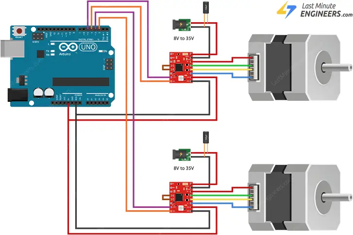
In this third example, we’ll control two stepper motors simultaneously. Doing this manually without a library can be very tricky, but with the help of the AccelStepper library, it becomes much easier and more manageable.
Wiring
To get started, you’ll need to add a second NEMA 17 stepper motor to your setup.
Just like the first motor, this second one also needs its own A4988 driver board. The wiring for the second driver is nearly identical to the first one, except you’ll need to connect the STEP and DIR pins of the second driver to two different Arduino pins. In this example, we’ll use pin 5 for STEP and pin 4 for DIR. Once you have both drivers wired correctly, you’re ready to upload the code.
The image below shows how to build the circuit.
Arduino Code
Here’s a sketch that makes both motors sweep back and forth across 360 degrees, but in opposite directions. Both motors will smoothly accelerate when they start moving and decelerate as they approach the end of their travel.
// Include the AccelStepper Library
#include <AccelStepper.h>

// Define motor interface type
#define motorInterfaceType 1

// Creates two instances
AccelStepper stepper1(motorInterfaceType, 3, 2);
AccelStepper stepper2(motorInterfaceType, 5, 4);

void setup() {
  // set the maximum speed, acceleration factor,
  // initial speed and the target position for motor 1
  stepper1.setMaxSpeed(1000);
  stepper1.setAcceleration(50);
  stepper1.setSpeed(200);
  stepper1.moveTo(200);

  // set the same for motor 2
  stepper2.setMaxSpeed(1000);
  stepper2.setAcceleration(50);
  stepper2.setSpeed(200);
  stepper2.moveTo(-200);
}

void loop() {
  // Change direction once the motor reaches target position
  if (stepper1.distanceToGo() == 0)
    stepper1.moveTo(-stepper1.currentPosition());
  if (stepper2.distanceToGo() == 0)
    stepper2.moveTo(-stepper2.currentPosition());

  // Move the motor one step
  stepper1.run();
  stepper2.run();
}
Code Explanation:
The code starts by including the AccelStepper library, just as we did in the previous example.
#include <AccelStepper.h>Next, we specify the motor interface type, which tells the library we’re using stepper drivers with STEP and DIR pins.
// Define motor interface type
#define motorInterfaceType 1
We then create two instances of the AccelStepper class—one for each motor. For each instance, we specify the motor interface type and the Arduino pins connected to the STEP and DIR inputs of each driver.
AccelStepper stepper1(motorInterfaceType, 3, 2);
AccelStepper stepper2(motorInterfaceType, 5, 4);
In the setup() function, we configure several important settings for both motors:
- We set the maximum speed to 1000 steps per second for both motors
- We define acceleration values to control how quickly each motor speeds up or slows down
- We set an initial speed for each motor using setSpeed()
- We give each motor its own target position using moveTo()
Since our stepper motors require 200 steps for one complete rotation, we use 200 as the target value for the first motor. To make the second motor spin in the opposite direction, we set its target to -200.
void setup() {
  // settings for motor 1
  stepper1.setMaxSpeed(1000);
  stepper1.setAcceleration(50);
  stepper1.setSpeed(200);
  stepper1.moveTo(200);

  // settings for motor 2
  stepper2.setMaxSpeed(1000);
  stepper2.setAcceleration(50);
  stepper2.setSpeed(200);
  stepper2.moveTo(-200);
}
In the loop() function, we use two separate if statements—one for each motor—to check whether each motor has reached its target position. We do this using the distanceToGo() function, which returns zero when the motor reaches its destination. At that point, we reverse the motor’s direction by setting its target to the negative of its current position, creating a continuous back-and-forth motion.
Finally, and most importantly, we call the run() function for each motor. This step is absolutely essential—without these calls, neither motor will move, even if you’ve set speeds and targets.
void loop() {
  // Change direction once the motor reaches target position
  if (stepper1.distanceToGo() == 0)
    stepper1.moveTo(-stepper1.currentPosition());
  if (stepper2.distanceToGo() == 0)
    stepper2.moveTo(-stepper2.currentPosition());

  // Move the motor one step
  stepper1.run();
  stepper2.run();
}