
If you’ve been tinkering with Arduino for a while, chances are you’ve come across dot matrix displays. They’re everywhere, from stock tickers and digital clocks to massive outdoor billboards. Behind many of these displays is a small but powerful chip: the MAX7219.
The MAX7219 is a popular and reliable way to control LED dot matrix displays with ease. It can handle up to 64 individual LEDs (an 8×8 grid) using just three data pins on your Arduino. Even better, it supports daisy-chaining, which means you can connect multiple displays in a row to create much larger visual projects—perfect for signs, counters, or message boards.
Whether you want to display simple messages, make a mini scoreboard, or build a scrolling display, the MAX7219 module makes the process both simple and fun. In this tutorial, we’ll walk through how these displays work, how to connect one to your Arduino, and how to write code to control it.
Let’s dive in and light things up!
MAX7219 Module Overview
There are several types of MAX7219 modules, but the two most common are the generic module and the FC-16 module.

These modules usually include an 8×8 LED dot matrix display and a MAX7219 breakout board. Let’s break down what each part does and how they work together.
The Dot Matrix Display

An 8×8 dot matrix display contains 64 small LEDs arranged in a grid with 8 rows and 8 columns. You might think controlling all these LEDs would require 64 separate wires (one for each LED), plus additional wires for power—but that would be way too complicated!
Instead, the display uses a technique called Multiplexing. This clever method connects the rows and columns in a matrix pattern, reducing the number of control pins to just 16—8 pins for the rows and 8 pins for the columns.

With multiplexing, the display lights up just one row at a time. While that row is active, the appropriate columns are also activated to light up the desired LEDs in that row. This means no more than eight LEDs are lit at any moment.
The display rapidly switches between rows—hundreds or thousands of times per second! Due to the human eye’s persistence of vision, this rapid cycling makes it appear as if all the LEDs are lit up at the same time.
The MAX7219 Breakout Board
Multiplexing is great, but it can be challenging to manage because your microcontroller would need to constantly refresh the display to keep the image stable.
This is where the MAX7219 chip becomes super helpful! It takes care of refreshing the display automatically, so you don’t have to worry about it.

All you need to do is send simple commands through SPI, using just three data wires (plus one for ground). Once the chip receives your data, it handles refreshing the display by itself—up to 800 times per second—and keeps the brightness of the LEDs steady. This frees up your microcontroller to handle other important tasks.
The MAX7219 chip includes some awesome features:
- Power-saving mode: You can turn off the display when not needed to save energy.
- Startup safety: The chip keeps all LEDs off for the first few seconds when powering up, preventing random flickering or strange patterns during startup.
- Daisy-chaining: If you want a larger display, you can connect multiple MAX7219 modules together using the same 3 SPI data wires. This allows you to create longer scrolling text displays or build bigger visual projects easily!
Adjusting Brightness and Current on the MAX7219 Module
The MAX7219 chip allows you to adjust the brightness of the display in two different ways: through hardware or through software. Let’s explore both methods.
Hardware Brightness Control
On your MAX7219 breakout board, you’ll find a resistor called RSet. This resistor controls the amount of current that flows through each LED, which directly affects the overall brightness of the display.

Different LED displays need different resistor values depending on what type of LEDs they use. For example, if you have a Red LED matrix with LEDs that need 2V and 20mA of current, you would use a 28kΩ resistor.
The table below shows which resistor values to use, based on the voltage and current needed by the LEDs in your matrix display.
| ISEG (mA) | VLED (V) | ||||
| 1.5 | 2.0 | 2.5 | 3.0 | 3.5 | |
| 40 | 12.2 | 11.8 | 11.0 | 10.6 | 9.69 |
| 30 | 17.8 | 17.1 | 15.8 | 15.0 | 14.0 |
| 20 | 29.8 | 28.0 | 25.9 | 24.5 | 22.6 |
| 10 | 66.7 | 63.7 | 59.3 | 55.4 | 51.2 |
Software Brightness Control
You can also change the brightness directly in your code. We’ll show you exactly how to do this later in the tutorial when we start programming the display.
MAX7219 Module Pinout
No matter which type of MAX7219 module you’re using (generic or FC-16), it will have two sets of pins:

Input Connector
These are the pins you use to connect the module to your microcontroller (like an Arduino):
VCC is the power supply pin. Connect it to a 5V power supply. Since the display can use quite a lot of power (up to 1A at full brightness), it’s best to use a separate power supply. If you want to use the Arduino’s 5V pin instead, keep the brightness low (below 25%) to avoid overheating the voltage regulator.
GND is the ground pin. This needs to be connected to the common ground.
DIN is the data input pin. You can connect this to any digital pin on your Arduino.
CS is the chip select pin. This also connects to a digital pin on your Arduino.
CLK is the clock pin. This connects to another digital pin.
Output Connector
The second set of pins is used when you want to connect multiple displays together in a chain (daisy-chaining):
VCC connects to the VCC pin on the next module.
GND connects to the GND pin on the next module.
DOUT is the data output pin and connects to the DIN pin on the next module.
LOAD connects to the CS pin on the next module.
CLK connects to the CLK pin on the next module.
Wiring the MAX7219 Module with an Arduino
Now that we’ve learned how the MAX7219 module works, it’s time to connect it to an Arduino and get it running!
Let’s start with the power supply connections. As mentioned earlier, the display can use quite a lot of power (up to 1A at full brightness), so we’ll use a separate power supply instead of the Arduino board’s 5V supply.
If you’re only using a single generic-type MAX7219 module and keeping the brightness low, you can power it directly from the Arduino—but it’s generally safer not to.
Next, we’ll connect the pins used for SPI communication. Since the MAX7219 module needs to transfer data quickly, it works best when connected to the hardware SPI pins on your Arduino. For Arduino boards like the UNO or Nano V3.0, these pins are: digital 13 (SCK), 12 (MISO), 11 (MOSI), and 10 (CS).
If you’re using a different Arduino board, make sure to check the official Arduino documentation to find the correct hardware SPI pins for your specific model.
Here’s a quick reference table for the pin connections:
| MAX7219 Module | Arduino | |
| GND | GND | |
| DIN | 11 | |
| CS/LOAD | 3 | |
| CLK | 13 |
Here’s how to wire up the Generic MAX7219 Module:

Here’s how to wire up the FC-16 MAX7219 Module:

Daisy-Chaining Multiple Displays
If you want to create a larger display using multiple MAX7219 modules, you can easily daisy-chain them together. Just connect the DOUT pin of the first module to the DIN pin of the next module. Then share the VCC, GND, CLK, and CS connections across all displays.
Library Installation
Writing all the code for controlling the MAX7219 display from scratch would be complicated and time-consuming. Fortunately, there’s a helpful library called MD_Parola that makes things much easier.
To install the library,
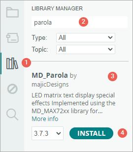
- First open your Arduino IDE program. Then click on the Library Manager icon on the left sidebar.
- Type “parola” in the search box to filter your results.
- Look for MD_Parola Library by MajicDesigns.
- Click the Install button to add it to your Arduino IDE.
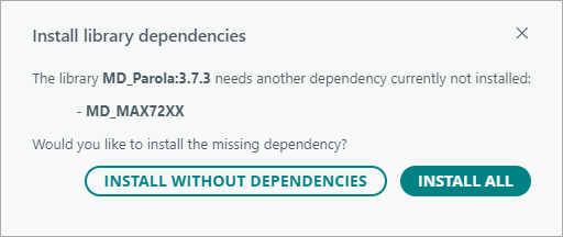
Since the MD_Parola Library depends on other libraries to function properly, you’ll be prompted to install these dependencies, which include the MD_MAX72XX Library.
When this message appears, simply click INSTALL ALL to ensure everything is set up correctly.
Arduino Example 1 – Displaying Text on the MAX7219 Module
In our first example, we’re going to display simple text on the MAX7219 LED display—without any animations or special effects. This will help us get familiar with how the display works and how to control it using Arduino.
Before you upload the code, there are two important variables you need to change in the sketch so it knows what kind of display hardware you’re using.
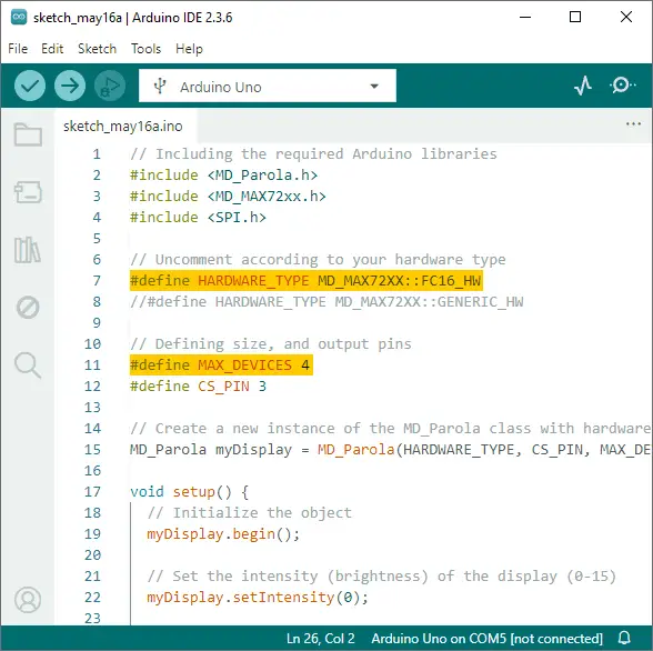
The first variable is HARDWARE_TYPE. This tells the Arduino which kind of MAX7219 module you are using.
- Set the
HARDWARE_TYPEtoGENERIC_HW, if your module has a green circuit board like the one shown below.
- Set the
HARDWARE_TYPEtoFC16_HW, if your module has a blue circuit board like the one shown below.
The second variable is MAX_DEVICES. This tells the Arduino how many MAX7219 chips are in your display. Each MAX7219 chip controls one 8×8 LED matrix. So, for example, if you are using an 8×32 display (which is four 8×8 matrices in a row), you would set MAX_DEVICES to 4.
Once you’ve updated those two variables, go ahead and upload the sketch to your Arduino.
// Including the required Arduino libraries
#include <MD_Parola.h>
#include <MD_MAX72xx.h>
#include <SPI.h>

// Uncomment according to your hardware type
#define HARDWARE_TYPE MD_MAX72XX::FC16_HW
//#define HARDWARE_TYPE MD_MAX72XX::GENERIC_HW

// Defining size, and output pins
#define MAX_DEVICES 4
#define CS_PIN 3

// Create a new instance of the MD_Parola class with hardware SPI connection
MD_Parola myDisplay = MD_Parola(HARDWARE_TYPE, CS_PIN, MAX_DEVICES);

void setup() {
  // Initialize the object
  myDisplay.begin();

  // Set the intensity (brightness) of the display (0-15)
  myDisplay.setIntensity(0);

  // Clear the display
  myDisplay.displayClear();
}

void loop() {
  myDisplay.setTextAlignment(PA_LEFT);
  myDisplay.print("Left");
  delay(2000);

  myDisplay.setTextAlignment(PA_CENTER);
  myDisplay.print("Center");
  delay(2000);

  myDisplay.setTextAlignment(PA_RIGHT);
  myDisplay.print("Right");
  delay(2000);

  myDisplay.setTextAlignment(PA_CENTER);
  myDisplay.setInvert(true);
  myDisplay.print("Invert");
  delay(2000);

  myDisplay.setInvert(false);
  myDisplay.print(1234);
  delay(2000);
}
Output
For your text to show up correctly, your display must be positioned properly:
- If you’re using a generic module, make sure the MAX7219 chip is at the top when looking at the display.
- If you’re using an FC-16 module, the side labeled DIN should be on the right side.
If everything is wired and oriented correctly, you should see the words “Left”, “Center”, “Right”, “Invert”, and the number “1234” displayed one after the other, with a short pause between each.
Code Explanation
The sketch begins by including all the necessary libraries. The MD_Parola and MD_MAX72xx libraries help control the display and handle text effects, while the SPI library allows communication between the Arduino and the MAX7219 chip.
#include <MD_Parola.h>
#include <MD_MAX72xx.h>
#include <SPI.h>
Next, we tell the program what type of module we’re using by setting the HARDWARE_TYPE. Since we’re using the FC-16 type module in this example, we set it to FC16_HW. Then we set MAX_DEVICES to 4, because an FC-16 module has four 8×8 LED matrices in a row. Finally, we define the CS_PIN, which is the pin on the Arduino that connects to the CS (Chip Select) pin on the MAX7219 module. In this example, we’re using digital pin 3.
#define HARDWARE_TYPE MD_MAX72XX::FC16_HW
#define MAX_DEVICES 4
#define CS_PIN 3
After that, we create a new object of the MD_Parola class. This object will help us control the display. When we make it, we pass in the hardware type, the CS pin, and the number of devices.
MD_Parola myDisplay = MD_Parola(HARDWARE_TYPE, CS_PIN, MAX_DEVICES);In the setup() function, we get everything ready. First, we initialize the display using the begin() function. Then we set the brightness of the LEDs using setIntensity(brightness). The brightness can range from 0 (very dim) to 15 (very bright). In this case, it’s set to 0 to keep power usage low. Finally, we clear the display using the displayClear() function to ensure it starts with a blank screen.
void setup() {
  myDisplay.begin();
  myDisplay.setIntensity(0);
  myDisplay.displayClear();
}
Now in the loop() function, we show different messages.
First, we align the text to the left using setTextAlignment(PA_LEFT) and display the word “Left” using print("Left"). Then we wait 2 seconds.
myDisplay.setTextAlignment(PA_LEFT);
myDisplay.print("Left");
delay(2000);
Next, we change the alignment to center, and show the word “Center”. After another pause, we switch the alignment to right, and show the word “Right”.
myDisplay.setTextAlignment(PA_CENTER);
myDisplay.print("Center");
delay(2000);

myDisplay.setTextAlignment(PA_RIGHT);
myDisplay.print("Right");
delay(2000);
After that, we switch the alignment back to center again and turn on the invert effect using setInvert(true). Then we show the word “Invert”.
myDisplay.setTextAlignment(PA_CENTER);
myDisplay.setInvert(true);
myDisplay.print("Invert");
delay(2000);
Finally, we turn off the invert effect using setInvert(false) and display the number 1234. Since it’s a number and not a word, we don’t use quotation marks this time.
myDisplay.setInvert(false);
myDisplay.print(1234);
delay(2000);
Arduino Example 2 – Scrolling Text on the MAX7219 Display
Sometimes, you want to show a longer message on the LED matrix, but the display just isn’t wide enough to fit it all at once. That’s where the scrolling text effect comes in. In this example, we’ll show you how to scroll a message across the screen so the entire text can be seen.
Go ahead and upload the sketch to your Arduino. You should see the word “Hello” scroll smoothly across your LED matrix from right to left.
// Including the required Arduino libraries
#include <MD_Parola.h>
#include <MD_MAX72xx.h>
#include <SPI.h>

// Uncomment according to your hardware type
#define HARDWARE_TYPE MD_MAX72XX::FC16_HW
//#define HARDWARE_TYPE MD_MAX72XX::GENERIC_HW

// Defining size, and output pins
#define MAX_DEVICES 4
#define CS_PIN 3

// Create a new instance of the MD_Parola class with hardware SPI connection
MD_Parola myDisplay = MD_Parola(HARDWARE_TYPE, CS_PIN, MAX_DEVICES);

void setup() {
  // Initialize the object
  myDisplay.begin();

  // Set the intensity (brightness) of the display (0-15)
  myDisplay.setIntensity(0);

  // Clear the display
  myDisplay.displayClear();

  myDisplay.displayScroll("Hello", PA_CENTER, PA_SCROLL_LEFT, 100);
}

void loop() {
  if (myDisplay.displayAnimate()) {
    myDisplay.displayReset();
  }
}
Once you upload the sketch to your Arduino, you should see:
Code Explanation
You’ll see that almost everything in this sketch—from the beginning of the code to the end of the setup() function—is just like the previous example. The main difference is that, at the end of the setup() function, we add the displayScroll() function. This function tells the display to scroll a message across the screen. In our example, the message we are scrolling is the word “Hello”.
myDisplay.displayScroll("Hello", PA_CENTER, PA_SCROLL_LEFT, 100);This function takes four arguments: displayScroll(pText, align, textEffect, speed)
pText– is the message you want to scroll.align– sets the alignment of the text. You can use the same alignment options as in the previous example, likePA_CENTER,PA_LEFT, orPA_RIGHT.textEffect– specifies the type of scrolling effect. Setting it toPA_SCROLL_LEFTscrolls the text from right to left across the display.speed- controls the scrolling speed, measured in milliseconds. Smaller numbers make it scroll faster.
Now, in the loop() function, we use two main functions to keep the text scrolling.
First, displayAnimate() is called to make the actual scrolling happen. This function automatically moves the text and returns true once the animation is complete. Then we use displayReset() to reset the scrolling animation back to the beginning so it can start again.
void loop() {
  if (myDisplay.displayAnimate()) {
    myDisplay.displayReset();
  }
}
Because these two functions are inside a loop() function, the “Hello” message will scroll across your display over and over again, creating a continuous scrolling effect.
If you want to try other cool effects (like scrolling up, down, or adding fades), you can check out the MD_Parola Library Reference on GitHub.