
If you’ve ever wanted to add buttons to your Arduino project—whether for entering a password, controlling a robot, or navigating a menu—a membrane keypad is a great place to start. These keypads are affordable, durable, and even water-resistant, which makes them perfect for many DIY electronics projects.
Membrane keypads come in several sizes, but the most common are the 4×3 keypad, and the 4×4 keypad. Their layout is similar to a telephone keypad, which makes them familiar and easy to use right away.

Even though they come in different sizes, all membrane keypads work the same way. Once you understand how they connect and communicate with an Arduino, you’ll be able to use them in all kinds of creative and useful ways.
So, let’s dive in and explore how these keypads work and how you can hook one up to your Arduino!
Membrane Keypad Construction
A membrane keypad is made from a thin, flexible material and usually has six main layers. These layers work together to let the keypad function properly. Here’s a breakdown of each layer:

Graphic Overlay – This is the top layer that you actually see and touch. It’s usually made of polyester because polyester lasts longer and bends better than alternatives like polycarbonate.
Metal Domes – Just beneath the top layer are small metal or plastic domes that give you a “click” feeling when you press a button.
Top Circuit Layer – This layer contains special electrical pathways made from polyester with silver-filled conductive ink printed on it. It extends into a flexible tail that connects the keypad to other electronic devices.
Spacer – This layer keeps the top and bottom circuit layers separated from each other. This ensures the button remains “off” until you press it. When you press a key, the top and bottom layers touch, allowing electricity to flow.
Bottom Circuit Layer – Similar to the top circuit layer, this layer also has electrical pathways made with silver-filled conductive ink. It also extends into a flexible tail for connecting to electronic devices.
Rear Adhesive Layer – The bottom layer is sticky, allowing you to attach the keypad to almost any surface. This makes membrane keypads very versatile and easy to install.
If you were to peel off the backing paper of a membrane keypad, you could see how all these layers are stacked together to form the complete keypad.

An interesting feature of membrane keypads is how the buttons are connected. All the rows and columns of buttons are wired together in a grid pattern. This clever design reduces the number of connection pins needed. For example, without this grid arrangement, a keypad with 16 buttons would need 17 connection pins (one for each button plus one for the ground). By arranging buttons in rows and columns, you only need 8 pins for the entire 4×4 keypad. This smart technique of controlling many buttons with fewer connection pins is called “Multiplexing.”
How Does the Matrix Keypad Work?
A matrix keypad is made up of buttons arranged in rows and columns. Each button sits exactly where a row and a column cross each other.
The diagram below shows how the wires inside a 4×3 matrix keypad connect each row to each column.

When you press a button, it connects one of the rows to one of the columns, allowing electricity to flow between them. For example, if you press the ‘4’ key, it connects column 1 and row 2.

By figuring out which row is connected to which column, we can tell exactly which button was pressed.
Keypad Scanning
To detect which button is pressed, the microcontroller uses a technique called “scanning“. Here’s how it works:
- First, the microcontroller sets the row lines as outputs and the column lines as inputs.
- It then enables pull-up resistors on the column lines. These resistors make sure the columns normally read as HIGH. If something connects a column to ground, that column will read as LOW.
- The microcontroller then sends a LOW signal to one row at a time, while keeping all other rows HIGH. Then it checks each column to see if any of them have also gone LOW.
- If both a row and a column are LOW at the same time, it means the button at their crossing point has been pressed.
- For example, if the microcontroller sends a LOW signal to the second row and finds that the second column has also gone LOW, it knows that the button “5” (at the crossing point of row 2 and column 2) has been pressed.
- Once a button press is detected, the microcontroller waits for the button to be released. Then it figures out exactly which character was pressed by looking it up in a special list called a keymap array. This array tells it what character (like ‘4’, ‘A’, ‘#’, etc.) belongs to each row-column combination.
This scanning process is done very quickly and is repeated for each row in turn. This way, the microcontroller can catch any key press almost instantly when it happens.
4×3 and 4×4 Membrane Keypad Pinout
The membrane keypad comes with a female Dupont connector. When you’re looking at the front of the keypad, the row pins are on the left, and the column pins are on the right.
Here’s how the pins are arranged:


Connecting a 4×3 and a 4×4 Membrane Keypad to an Arduino
Now that you understand how the membrane keypad works, it’s time to connect it to an Arduino board. This is actually pretty easy because the order of the keypad pins matches the order of the Arduino pins you’ll use.
Start by connecting keypad pin 1 to Arduino digital pin 9. Then keep connecting each following keypad pin to the next Arduino digital pin: pin 2 to pin 8, pin 3 to pin 7, and so on, until all pins are connected.
The table below shows the full list of connections:
| Keypad | Arduino | |
| R1 | 9 | |
| R2 | 8 | |
| R3 | 7 | |
| R4 | 6 | |
| C1 | 5 | |
| C2 | 4 | |
| C3 | 3 | |
| C4 | 2 |
Note: The highlighted connection in the table only applies to 4×4 keypads, since the 4×3 keypad has one less column.
The easiest and cleanest way to connect the keypad to the Arduino is by using an 8-pin male-to-male Dupont ribbon cable. This type of cable makes the setup neat and avoids confusion with wiring.


Library Installation
To figure out which key on the keypad was pressed, the program needs to constantly scan all the rows and columns. Luckily, there’s no need to do this manually. A special library called Keypad was created to handle this automatically and make things much easier.
To install the library,
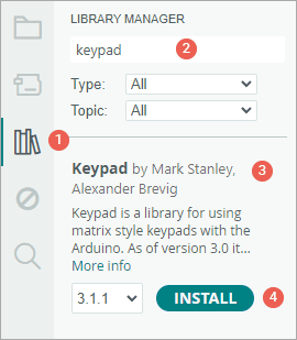
- First open your Arduino IDE program. Then click on the Library Manager icon on the left sidebar.
- Type “keypad” in the search box to filter your results.
- Look for the Keypad Library by Mark Stanley, Alexander Brevig.
- Click the Install button to add it to your Arduino IDE.
Arduino Example Code
The basic Arduino sketch below detects which key on a keypad is pressed and displays it on the Serial Monitor.
Code for 4×3 Keypad
#include <Keypad.h>

const byte ROWS = 4;  //four rows
const byte COLS = 3;  //three columns

char keys[ROWS][COLS] = {
  { '1', '2', '3' },
  { '4', '5', '6' },
  { '7', '8', '9' },
  { '*', '0', '#' }
};
byte rowPins[ROWS] = { 9, 8, 7, 6 };  //connect to the row pinouts of the keypad
byte colPins[COLS] = { 5, 4, 3 };     //connect to the column pinouts of the keypad

//Create an object of keypad
Keypad keypad = Keypad(makeKeymap(keys), rowPins, colPins, ROWS, COLS);

void setup() {
  Serial.begin(9600);
}

void loop() {
  char key = keypad.getKey();  // Read the key

  // Print if key pressed
  if (key) {
    Serial.print("Key Pressed : ");
    Serial.println(key);
  }
}
Code for 4×4 Keypad
#include <Keypad.h>
const byte ROWS = 4; //four rows
const byte COLS = 4; //four columns
char keys[ROWS][COLS] = {
{ '1', '2', '3', 'A' },
{ '4', '5', '6', 'B' },
{ '7', '8', '9', 'C' },
{ '*', '0', '#', 'D' }
};
byte rowPins[ROWS] = { 9, 8, 7, 6 }; //connect to the row pinouts of the keypad
byte colPins[COLS] = { 5, 4, 3, 2 }; //connect to the column pinouts of the keypad
//Create an object of keypad
Keypad keypad = Keypad(makeKeymap(keys), rowPins, colPins, ROWS, COLS);
void setup() {
Serial.begin(9600);
}
void loop() {
char key = keypad.getKey(); // Read the key
// Print if key pressed
if (key) {
Serial.print("Key Pressed : ");
Serial.println(key);
}
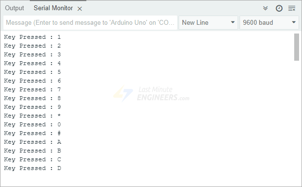
}After uploading the sketch to your Arduino, open the Serial Monitor and set the speed to 9600 baud. When you press any button on the keypad, you’ll see the corresponding character appear on the screen.
Code Explanation
At the beginning of the sketch, we include the Keypad library. This gives us access to built-in functions that make working with keypads much easier.
#include <Keypad.h>Next, we define the size of our keypad by specifying how many rows and columns it has. If your keypad has a different layout, you’ll need to adjust these numbers to match your hardware.
const byte ROWS = 4; //four rows
const byte COLS = 4; //four columns
We then create a keymap array called keys. This two-dimensional array stores all the characters we want to display when buttons are pressed.
char keys[ROWS][COLS] = {
  { '1', '2', '3', 'A' },
  { '4', '5', '6', 'B' },
  { '7', '8', '9', 'C' },
  { '*', '0', '#', 'D' }
};
In this example the characters are arranged in the array just like they are on the keypad itself. However, you can customize the keymap array to suit different projects.
For example, if you’re making a calculator, you might want to change the characters to include math symbols. Instead of the default setup, you could define your array like this:
char keys[ROWS][COLS] = {
  {'1','2','3','4'},
  {'5','6','7','8'},
  {'9','0','+','-'},
  {'.','*','/','='}
};
After that, we define two more arrays, rowPins and colPins. These arrays tell the Arduino which of its digital pins connect to the keypad’s rows and columns. It’s important to list these pins in the same order as your wiring connections so the program can correctly identify which key was pressed.
byte rowPins[ROWS] = {9, 8, 7, 6}; //connect to the row pinouts of the keypad
byte colPins[COLS] = {5, 4, 3, 2}; //connect to the column pinouts of the keypad
We then create a keypad object using the Keypad library. This object makes it easy to check which button is being pressed without having to manually scan the hardware ourselves. The keypad object needs five pieces of information: the keymap, the row pins, the column pins, and the number of rows and columns.
//Create an object of keypad
Keypad keypad = Keypad( makeKeymap(keys), rowPins, colPins, ROWS, COLS );
Inside the setup() function, we initialize the serial communication.
void setup(){
  Serial.begin(9600);
}
In the loop(), the getKey() method continuously checks if any key is being pressed. When it detects a pressed key, it saves that key in a variable and prints it to the Serial Monitor. If no key is pressed, the program simply keeps checking.
void loop() {
  char key = keypad.getKey();  // Read the key

  // Print if key pressed
  if (key) {
    Serial.print("Key Pressed : ");
    Serial.println(key);
  }
}
Some Useful Functions of the Keypad Library
The Keypad library comes with several helpful functions that you can use with your keypad object. These functions give you more control over how the keypad behaves and how your program responds to key presses. Here are some of the most useful ones:
- The function
char waitForKey()pauses your program and waits until someone presses a key on the keypad. While waiting, it won’t run any other parts of your code (except for interrupt routines). Be careful with this function since it prevents the rest of your program from running until someone presses a key. - The function
KeyState getState()returns the current state of a key. There are four possible states:IDLE,PRESSED,RELEASED, andHOLD. - The function
boolean keyStateChanged()lets you check if a key’s state has changed recently. For example, this tells you if a key went from being pressed to being released, or from pressed to being held down. - The function
setHoldTime(unsigned int time)lets you set how long (in milliseconds) a key needs to be held down before it’s considered in the HOLD state. - The function
setDebounceTime(unsigned int time)sets the amount of time (in milliseconds) the keypad will wait before accepting another key press. This helps avoid accidental double-presses caused by the button bouncing. - The function
addEventListener(keypadEvent)allows you to set up an event that gets triggered automatically whenever someone uses the keypad.