
Whether you’re building a digital clock, logging sensor data with timestamps, or automating something based on time of day, you’ll need a way to track time accurately.
That’s where the DS3231 Real-Time Clock (RTC) module comes in. Known for its precision and reliability, the DS3231 is the go-to choice when your project can’t afford to lose track of time.
In this tutorial, we’ll walk you through everything you need to know to get started with the DS3231 module. You’ll learn how it works, how to hook it up to your Arduino, and how to set and read the current date, time, and temperature from it. We’ll also explore how to use the onboard EEPROM for storing extra data.
Let’s get started and give your Arduino the power to tell time like a pro!
Hardware Overview
DS3231 RTC Chip
At the heart of the module is the DS3231 – a low-cost, highly accurate I2C-based RTC chip made by Maxim Integrated.

The DS3231 can keep track of seconds, minutes, hours, days, dates, months, and years. It’s smart enough to know which months have fewer than 31 days and adjusts automatically. It also handles leap years correctly—though only up to the year 2100.
You can set up the chip to show time in either 12-hour format (with AM/PM indicators) or 24-hour format. The chip also includes two programmable alarms that can go off at specific times during the day.
The chip has a special pin called INT/SQW that can do two different things. It can either send out an interrupt signal when an alarm goes off, or it can produce a steady square wave signal at one of four frequencies: 1Hz, 4kHz, 8kHz, or 32kHz.
There’s another pin called the 32K pin that outputs an extremely stable and accurate timing signal. This signal stays precise even when the temperature changes, which makes it useful for applications that need exact timing or for keeping other electronic circuits synchronized.
Temperature Compensated Crystal Oscillator(TCXO)
Most other RTC modules, like the DS1307, need an external 32kHz crystal oscillator to keep time. The problem with these crystals is that their frequency can change slightly with temperature. This tiny change might not seem like much, but over days and weeks, your clock could end up being minutes off!
The DS3231 solves this problem by using a built-in 32kHz temperature-compensated crystal oscillator (TCXO), which is highly resistant to changes in temperature. This helps the clock stay accurate over time.

The TCXO consists of three key parts working together: a temperature sensor, a 32kHz crystal oscillator, and control logic. If the temperature causes the crystal’s frequency to change, the chip automatically adjusts the clock by adding or removing ticks to keep it accurate.
Thanks to the TCXO, the DS3231 can maintain an accuracy of about ±2 minutes per year, making it one of the most reliable RTC modules available.
DS3231 Vs DS1307
The main difference between the DS3231 and DS1307 RTC modules is how accurately they keep time.
The DS1307 relies on an external 32kHz crystal to keep time. However, the problem with this crystal is that its frequency can change when the temperature around it changes. Because of this sensitivity to temperature, the DS1307 clock typically drifts about five minutes per month from the actual time.
The DS3231, on the other hand, is much more accurate because it has a built-in Temperature Compensated Crystal Oscillator (TCXO). This special built-in crystal system can detect changes in temperature and automatically adjust itself to keep the correct time. As a result, the DS3231 only drifts by about ±2 minutes per year at most.
This doesn’t mean the DS1307 is a bad choice—it’s still a reliable RTC for many basic projects. It is also usually less expensive. But if your project requires more precise timekeeping, the DS3231 is definitely the better option.
Battery Backup
The DS3231 chip has a battery backup feature that keeps the clock running accurately even when the main power is disconnected.
On the back of the module, you’ll find a battery holder designed for a 20mm 3V lithium coin cell battery.

Inside the chip, there’s a built-in smart power-sensing circuit that constantly checks the main power. If this circuit detects that the main power has been lost, it automatically switches to the backup battery.
Warning:
These modules usually come with a 200Ω resistor soldered next to a 1N4148 diode (which you can see in the image). Together, these components form a simple charging circuit designed for rechargeable LIR2032 batteries.

However, some DS3231 modules come with non-rechargeable CR2032 batteries instead. If your module has a non-rechargeable battery, you must remove the resistor! Attempting to charge a non-rechargeable battery is dangerous. It can damage the battery and may even cause it to leak or explode!
Onboard 24C32 EEPROM
In addition to the main DS3231 chip, the module also includes a 24C32 EEPROM chip. EEPROM stands for Electrically Erasable Programmable Read-Only Memory. While this chip isn’t used for timekeeping, it’s handy for storing data—like logs or settings—that you want to keep even when the power is turned off.
The 24C32 EEPROM can store 32 kilobits of data, and it’s designed to handle up to 1,000,000 write cycles, meaning you can save data many times before it wears out.

This EEPROM uses the I2C communication protocol, just like the DS3231 chip, and both share the same I2C bus. If you’re using other devices on the same I2C bus, you might need to change the EEPROM’s address to avoid conflicts.
For this purpose, the module comes with three solder jumpers on the back labeled A0, A1, and A2. By adding a blob of solder to short a jumper, you can change the address of the EEPROM.

According to the 24C32 datasheet, the three address bits are located at the end of the 7-bit I2C address register (right before the Read/Write bit).

Since there are three address inputs that can be either HIGH or LOW, you can create eight different address combinations (2^3 = 8).
All three address inputs are pulled HIGH by default using onboard pullup resistors. This gives the EEPROM a default I2C address of 0x57.
When you short a solder jumper, you pull that address input LOW. If you were to short all three jumpers, the address would change to 0x50. So the range of possible addresses goes from 0x50 to 0x57.
You can set different I2C addresses according to this table:

I2C Interface
The DS3231 module uses the I2C protocol to communicate with microcontrollers, such as Arduino or Raspberry Pi. When you connect this module to your project, it uses two different I2C addresses:
- The DS3231 RTC chip has a fixed I2C address of 0x68.
- The EEPROM chip has a default I2C address of 0x57, but you can change it to any address between 0x50 and 0x57 using the solder jumpers.

The I2C signals, SDA and SCL, along with power and ground connections, are broken out on both sides of the board. This makes it easy to connect the module or even chain it to other I2C devices.
Technical Specifications
Here are the specifications:
| Operating Voltage | 2.3 to 5.5V (3.3 or 5V typical) |
| Current Consumption | < 300µA (typ.) |
| Accuracy (0-40°C) | ± 2ppm |
| Battery | CR2032 (3V Coin) |
For more information on the DS3231 RTC and the 24C32 EEPROM chip, please refer to the datasheets provided below.
DS3231 RTC Module Pinout
The DS3231 RTC module has 6 pins in total. The pinout is as follows:

32K pin provides a stable 32.768kHz square wave signal. This can be used as a clock reference for other devices if needed.
INT/SQW is the Interrupt/Square Wave output pin. It can be configured to act as an interrupt signal triggered by the RTC alarms, or to output a square wave at frequencies 1 Hz, 4 kHz, 8 kHz, or 32 kHz.
SCL is a serial clock pin for the I2C communication.
SDA is a serial data pin for the I2C communication.
VCC is the power supply pin. It can be connected to either 3.3V or 5V depending on your microcontroller, as the module is designed to handle both voltage levels.
GND is the ground pin.
Wiring a DS3231 RTC module to an Arduino
Let’s connect the DS3231 module to an Arduino! The wiring process is simple and requires just a few steps.
First, connect the VCC pin on the module to the Arduino’s 5V output and the GND pin to the Arduino’s ground.
Next, we need to connect the pins used for I2C communication. It’s important to know that different Arduino boards have different I2C pins, and these must be connected correctly. On Arduino boards with the R3 layout, the SDA and SCL pins are also found on the pin headers near the AREF pin. However, internally, they are the same as the A4 (SDA) and A5 (SCL) pins.
Here’s a quick reference table for the pin connections:
| DS3231 Module | Arduino | |
| VCC | 5V | |
| GND | GND | |
| SCL | SCL or A5 | |
| SDA | SDA or A4 |
Please refer to the image below to see the proper wiring setup.

Library Installation
To use the DS3231 module in our projects, we’ll use a special library called uRTCLib. This library makes reading time data from the RTC super simple.
Even though uRTCLib is easy to use, it’s also very powerful. Unlike many other RTC libraries, it supports time-of-day alarms and lets you control the SQW (Square Wave) output.
To install the library,
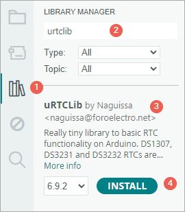
- First open your Arduino IDE program. Then click on the Library Manager icon on the left sidebar.
- Type “urtclib” in the search box to filter your results.
- Look for the uRTCLib Library by Naguissa.
- Click the Install button to add it to your Arduino IDE.
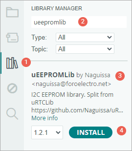
Later in the tutorial, we’ll also show you how to read from and write to the onboard 24C32 EEPROM chip. If you’re interested in trying that, you’ll also need to install another library called uEEPROMLib.
To install that one: Just search for “uEEPROMLib” in the Library Manager the same way, and click Install.
Arduino Code – Reading Date, Time, and Temperature
In this example, we’re using a simple Arduino sketch to set and read the date, time, and temperature from the DS3231 RTC module.
#include "Arduino.h"
#include "uRTCLib.h"
// uRTCLib rtc;
uRTCLib rtc(0x68);
char daysOfTheWeek[7][12] = { "Sunday", "Monday", "Tuesday", "Wednesday", "Thursday", "Friday", "Saturday" };
void setup() {
Serial.begin(9600);
URTCLIB_WIRE.begin();
// Comment out below line once you set the date & time.
// Following line sets the RTC with an explicit date & time
// for example to set April 14 2025 at 12:56 you would call:
rtc.set(0, 56, 12, 2, 14, 4, 25);
// rtc.set(second, minute, hour, dayOfWeek, dayOfMonth, month, year)
// set day of week (1=Sunday, 7=Saturday)
}
void loop() {
rtc.refresh();
Serial.print("Current Date & Time: ");
Serial.print(rtc.year());
Serial.print('/');
Serial.print(rtc.month());
Serial.print('/');
Serial.print(rtc.day());
Serial.print(" (");
Serial.print(daysOfTheWeek[rtc.dayOfWeek() - 1]);
Serial.print(") ");
Serial.print(rtc.hour());
Serial.print(':');
Serial.print(rtc.minute());
Serial.print(':');
Serial.println(rtc.second());
Serial.print("Temperature: ");
Serial.print(rtc.temp() / 100);
Serial.println("°C");
Serial.println();
delay(1000);
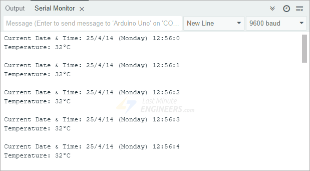
}Once the code is uploaded to your Arduino, open the serial monitor and set the baud rate to 9600 bps. You will see the current date and time in a nice format, followed by the temperature reading.
Code Explanation:
We start by including two important libraries: Arduino.h and uRTCLib.h. These help the Arduino communicate with the DS3231 chip.
#include "Arduino.h"
#include "uRTCLib.h"
Next, we create an RTC object using the uRTCLib library and define an array called daysOfTheWeek, which holds the names of the days from Sunday to Saturday.
// uRTCLib rtc;
uRTCLib rtc(0x68);

char daysOfTheWeek[7][12] = { "Sunday", "Monday", "Tuesday", "Wednesday", "Thursday", "Friday", "Saturday" };
Inside the setup() function, we open the Serial Monitor so we can print the date, time, and temperature readings to your screen. Then we use the URTCLIB_WIRE.begin() function to start the I2C communication.
URTCLIB_WIRE.begin();Then, we set the date and time manually using the rtc.set() function. You only need to run this once to set the correct date and time. After that, you should comment it out so it doesn’t reset every time you upload the code.
For example, the line rtc.set(0, 56, 12, 2, 14, 4, 25); sets the time to 12:56 PM on Monday, April 14, 2025. The values represent: seconds, minutes, hours, day of the week (1 = Sunday), day of the month, month, and last two digits of the year.
rtc.set(0, 56, 12, 2, 14, 4, 25);In the loop() function, we call the rtc.refresh() function to update the time and date values from the chip.
rtc.refresh();Then we print the current year, month, and day to the Serial Monitor. We also use the dayOfWeek() value as an index to print the name of the day from our daysOfTheWeek array.
Serial.print("Current Date & Time: ");
Serial.print(rtc.year());
Serial.print('/');
Serial.print(rtc.month());
Serial.print('/');
Serial.print(rtc.day());

Serial.print(" (");
Serial.print(daysOfTheWeek[rtc.dayOfWeek() - 1]);
Serial.print(") ");
After that, we print the hour, minute, and second to display the current time.
Serial.print(rtc.hour());
Serial.print(':');
Serial.print(rtc.minute());
Serial.print(':');
Serial.println(rtc.second());
Next, we read the built-in temperature sensor using the rtc.temp() function and print the temperature in degrees Celsius.
Serial.print("Temperature: ");
Serial.print(rtc.temp() / 100);
Serial.println("°C");
At the end of the loop, we add a 1-second delay so the data updates once every second.
Arduino Code – Reading and Writing to the 24C32 EEPROM
As you may already know, the DS3231 RTC module comes with a built-in 24C32 EEPROM chip that provides 32 kilobits of memory. That’s enough to store small bits of data like settings, passwords, sensor logs, or anything else you want to keep.
In this example, we’re going to write different types of data to the EEPROM and then read them back to make sure everything worked. We’ll try writing an integer, a float, a single character, and a string of text. You can expand this technique later to store more useful data based on your project.
#include "Arduino.h"
#include "Wire.h"
#include "uEEPROMLib.h"
// uEEPROMLib eeprom;
uEEPROMLib eeprom(0x57);
void setup() {
Serial.begin(9600);
Wire.begin();
int inttmp = 32123;
float floattmp = 3.1416;
char chartmp = 'A';
char c_string[] = "lastminuteengineers.com"; // 23 Characters
int string_length = strlen(c_string);
Serial.println("Writing into memory...");
// Write an int
if (!eeprom.eeprom_write(0, inttmp)) {
Serial.println("Failed to store int.");
} else {
Serial.println("int was stored correctly.");
}
// write a float
if (!eeprom.eeprom_write(4, floattmp)) {
Serial.println("Failed to store float.");
} else {
Serial.println("float was stored correctly.");
}
// Write single char at address
if (!eeprom.eeprom_write(8, chartmp)) {
Serial.println("Failed to store char.");
} else {
Serial.println("char was stored correctly.");
}
// Write a long string of chars FROM position 33 which isn't aligned to the 32 byte pages of the EEPROM
if (!eeprom.eeprom_write(33, (byte *) c_string, strlen(c_string))) {
Serial.println("Failed to store string.");
} else {
Serial.println("string was stored correctly.");
}
Serial.println("");
Serial.println("Reading memory...");
Serial.print("int: ");
eeprom.eeprom_read(0, &inttmp);
Serial.println(inttmp);
Serial.print("float: ");
eeprom.eeprom_read(4, &floattmp);
Serial.println((float) floattmp);
Serial.print("char: ");
eeprom.eeprom_read(8, &chartmp);
Serial.println(chartmp);
Serial.print("string: ");
eeprom.eeprom_read(33, (byte *) c_string, string_length);
Serial.println(c_string);
Serial.println();
}
void loop() {
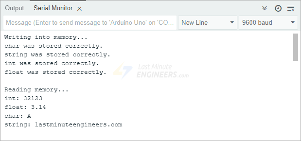
}Once the code is uploaded to your Arduino, open the serial monitor and set the baud rate to 9600 bps. The output on the Serial Monitor will display the values we wrote, proving that the EEPROM stores data safely.
Code Explanation:
We begin by including the Arduino.h, Wire.h, and uEEPROMLib.h libraries. These libraries allow the Arduino to communicate with the EEPROM over I2C.
#include "Arduino.h"
#include "Wire.h"
#include "uEEPROMLib.h"
Next, we create an EEPROM object using the default I2C address 0x57.
uEEPROMLib eeprom(0x57);Inside the setup() function, we initialize the Serial Monitor so we can see our results and begin the I2C connection with Wire.begin().
Wire.begin();We then define four variables: one for an integer, one for a float, one for a character, and a C-style string (which is just an array of characters). We also get the length of the string, so we know how many characters we’re storing.
int inttmp = 32123;
float floattmp = 3.1416;
char chartmp = 'A';
char c_string[] = "lastminuteengineers.com";  //23 Characters
int string_length = strlen(c_string);
To write data to the EEPROM, we use the eeprom_write() function. We give it a memory address and the value we want to store. Each time we write, we check whether it was successful and print a message to confirm.
We store the integer at address 0, the float at address 4, the character at address 8, and the string starting at address 33. The reason we start the string at a higher address is to avoid overlapping with other data already stored in lower memory locations.
// Write an int
if (!eeprom.eeprom_write(0, inttmp)) {
  Serial.println("Failed to store int.");
} else {
  Serial.println("int was stored correctly.");
}

// write a float
if (!eeprom.eeprom_write(4, floattmp)) {
  Serial.println("Failed to store float.");
} else {
  Serial.println("float was stored correctly.");
}

// Write single char at address
if (!eeprom.eeprom_write(8, chartmp)) {
  Serial.println("Failed to store char.");
} else {
  Serial.println("char was stored correctly.");
}

// Write a long string of chars FROM position 33 which isn't aligned to the 32 byte pages of the EEPROM
if (!eeprom.eeprom_write(33, (byte *)c_string, strlen(c_string))) {
  Serial.println("Failed to store string.");
} else {
  Serial.println("string was stored correctly.");
}
After writing, we move on to reading the data back using the eeprom_read() function. We print out the values one by one to verify that everything was saved correctly.
Serial.print("int: ");
eeprom.eeprom_read(0, &inttmp);
Serial.println(inttmp);

Serial.print("float: ");
eeprom.eeprom_read(4, &floattmp);
Serial.println((float)floattmp);

Serial.print("char: ");
eeprom.eeprom_read(8, &chartmp);
Serial.println(chartmp);

Serial.print("string: ");
eeprom.eeprom_read(33, (byte *)c_string, string_length);
Serial.println(c_string);
Note:
When writing to EEPROM, it’s important to understand how much space different types of data take up:
That means you need to be careful about where you store each type of data. For example, if you store an integer at address 0, you shouldn’t store anything else at address 1 because integers use two bytes. Instead, you’d store the next value at address 2 or higher. So, for storing multiple integers, you’d use memory addresses like 0, 2, 4, 6, and so on.
This helps prevent data from overlapping or getting corrupted.