
Whether you’re building a fitness tracker, developing a health-monitoring wearable, or just curious about how your heart beats, the MAX30100 is a compact and powerful sensor that brings real-time biometric data to your fingertips—literally. This low-power, I2C-based module can measure both heart rate and blood oxygen levels (SpO2).
Thanks to its simple interface and wide availability, the MAX30100 is a great tool for students, hobbyists, engineers, educators, and even mobile or game developers who want to add live health data to their projects.
In this hands-on tutorial, you’ll learn how the MAX30100 sensor works, how to wire it up to an Arduino, and explore several practical examples, including presence detection, temperature reading, heart rate, and blood oxygen monitoring.
Let’s get started and bring your health-monitoring project to life—beat by beat!
MAX30100 Module Hardware Overview
At the center of the module is the MAX30100—a small but powerful sensor created by Analog Devices. This sensor is designed to measure both heart rate and blood oxygen levels (SpO2).
The sensor includes:
- Two special LEDs — one red and one infrared (IR) that shine light into your skin
- A photodetector — that measures how much light bounces back
- Special optics and signal processing — that make sure the measurements are accurate

Because it’s small, reliable, and doesn’t use much power, the MAX30100 is commonly used in health gadgets like fitness trackers and smartwatches.
Power Requirements
The MAX30100 needs two different voltages to work properly: 1.8 volts for the main chip and 3.3 volts for the red and IR LEDs. Don’t worry though – the module comes with built-in voltage regulators, so you only need to provide one power source and the module handles the rest.

One of the best things about the MAX30100 is how little power it uses. During normal operation, it only uses about 600 μA. When it’s not actively measuring (in standby mode), it uses just 0.7 μA! This makes it perfect for battery-powered devices.
Built-in Temperature Sensor
The MAX30100 also includes a built-in temperature sensor. This sensor helps improve the accuracy of heart rate and blood oxygen readings by adjusting for changes in surrounding temperature.
This temperature sensor is quite precise. It measures the sensor’s internal temperature (also called the “die” temperature) from -40°C to +85°C with an accuracy of ±1°C.
I2C Interface
To communicate with a microcontroller, the MAX30100 uses a simple two-wire I2C interface.
Note that the sensor has a fixed I2C address:
- 0xAE for writing data
- 0xAF for reading data
FIFO Buffer
The MAX30100 collects data faster than a microcontroller can process it. This can lead to problems, like losing important measurements if the microcontroller isn’t ready in time to read it. To avoid this problem, the sensor has a special memory storage called a FIFO buffer (which stands for “First In, First Out”). This buffer works like a temporary storage space. It allows the sensor to keep collecting heart rate and blood oxygen level data even when the microcontroller is busy. Later, when the microcontroller is ready, it can read all the stored measurements from the buffer.
The MAX30100’s buffer can hold up to 16 sets of readings. This gives the microcontroller plenty of time to finish other tasks before coming back for the data.
Interrupts
The MAX30100 features an interrupt function, allowing the sensor to send alerts to the microcontroller when certain events occur. There are five types of interrupts:
- Power Ready — alerts when the sensor is powered up or recovers from a power drop (brownout condition).
- SpO2 Data Ready — alerts when a new blood oxygen reading is available
- Heart Rate Data Ready — alerts when a new heart rate reading is available
- Temperature Ready — alerts when a temperature reading is complete
- FIFO Almost Full — warns when the FIFO buffer is nearly full and might soon start losing new data

These alerts are sent through a special pin called INT. This pin normally stays HIGH. When an interrupt occurs, the pin goes LOW and stays that way until the microcontroller checks and clears the interrupt.
Technical Specifications
Here are the technical specifications:
| Power supply | 3.3V to 5.5V |
| Current draw | ~600μA (during measurements) |
| ~0.7μA (during standby mode) | |
| Red LED Wavelength | 660nm |
| IR LED Wavelength | 880nm |
| Temperature Range | -40˚C to +85˚C |
| Temperature Accuracy | ±1˚C |
You can find extensive information for the MAX30100 sensor from the datasheet.
MAX30100 vs. MAX30102
Analog Devices has created an exciting upgrade with their new MAX30102 sensor. Compared to the older MAX30100, this new version offers several improvements that make it more powerful and efficient for measuring heart rate and blood oxygen levels.
- Memory Storage (FIFO Buffer): The MAX30102 comes with a bigger memory bank than its predecessor. While the MAX30100 could only store 16 samples of SpO2 (blood oxygen) and heart rate data, the MAX30102 can hold up to 32 samples! This allows the MAX30102 to hold more data before it needs to be processed, which is especially helpful if the microcontroller is busy doing other tasks.
- Better Light Detection: The MAX30102 has a higher-resolution ADC, which can read up to 18 bits of information, which allows it to recognize 262,144 different levels of light intensity. The older MAX30100 only had a 16-bit ADC. This means the MAX30102 can detect much smaller changes in the light passing through your skin, making it more accurate at measuring your heartbeat and oxygen levels.
- Power Efficiency: The MAX30102 uses a narrower LED pulse width than the MAX30100. What does this mean? Basically, the lights inside the sensor turn on for shorter periods of time when taking measurements. This might seem like a small change, but it makes a big difference in how much power the sensor uses. Using less power is extremely important for devices like fitness trackers and smartwatches that run on small batteries and need to last all day (or longer) between charges.
If you’re interested in working with the MAX30102 module, you can follow the tutorial linked below:

How MAX30100 Pulse Oximeter and Heart Rate Sensor Works?
The MAX30100 is an optical sensor that measures your heart rate and blood oxygen level using light. It has two special LEDs—one red and one infrared (IR)—and a photodetector.
You might wonder why this sensor needs two different colored lights. The reason is that these lights have different wavelengths: red light has a wavelength of 660 nanometers and infrared light has 880 nanometers. Because of these different wavelengths, they interact with our blood in different ways, which helps the sensor make two different measurements.

The MAX30100 works by shining both lights onto a thin part of your body, like your fingertip or earlobe. These areas are ideal because the skin is thin enough to allow the light to penetrate easily. As the light passes through your skin, some of it gets absorbed by your blood, while the rest reflects back. The photodetector on the sensor measures how much light returns. This process is known as Photoplethysmography (PPG), which simply means measuring changes in blood volume using light.
The MAX30100 does two main jobs: measuring your heart rate and your blood oxygen level (SpO2).
Measuring Your Heart Rate
Your blood carries oxygen with the help of a protein called hemoglobin. When hemoglobin is carrying oxygen (known as oxygenated hemoglobin, or HbO2), it absorbs more infrared light.
Every time your heart beats, fresh oxygen-rich blood flows into your finger. Since this blood is full of oxygenated hemoglobin, it absorbs more infrared light. This means less infrared light reflects back to the photodetector.
Between heartbeats, there’s a bit less oxygenated blood in your finger, so less infrared light gets absorbed, and more light reaches the detector.

By continuously shining the infrared light and measuring these changes in the amount of light detected, the sensor can see a pattern that matches your heartbeat. It counts these “pulses” of changing light intensity to calculate how many times your heart beats per minute – your heart rate!
Measuring Blood Oxygen Levels (Pulse Oximetry)
To measure the oxygen level in your blood, the MAX30100 cleverly uses both the red and infrared lights. The key idea here is that oxygenated hemoglobin (HbO2) and deoxygenated hemoglobin (Hb) absorb light differently:
- Oxygenated hemoglobin absorbs more infrared light (880nm)
- Deoxygenated hemoglobin absorbs more red light (660nm)
The absorption-spectrum graph below shows how oxygenated hemoglobin and deoxygenated hemoglobin absorb different wavelengths of light at different rates.

By comparing how much red light and how much infrared light is absorbed, the MAX30100 can calculate what percentage of your hemoglobin is carrying oxygen. This percentage is your SpO2 level, which indicates how well-oxygenated your blood is.
MAX30100 Module Pinout
Let’s take a closer look at what each pin does:

VIN is the power input pin. You can connect it to either 3.3V or 5V, depending on what logic your microcontroller is based off of.
SCL is the clock pin used for I2C communication.
SDA is the data pin used for I2C communication.
INT is the interrupt pin. The MAX30100 can be configured to generate an interrupt when certain events occur, as explained earlier. This pin normally stays HIGH, but it goes LOW when an interrupt occurs and stays LOW until the microcontroller reads and clears the interrupt.
IRD is the ground connection for the infrared LED inside the module. You don’t need to connect anything to this pin – it’s handled internally by the chip.
RD Similar to IRD, this is the ground connection for the red LED inside the module. Leave this pin unconnected too.
GND is the ground pin.
MAX30100 Not Working – Problem and Solutions to Fix It
The MAX30100 module is very popular among hobbyists because it’s affordable and great for measuring heart rate and blood oxygen levels. However, many versions of this module have a design flaw that can prevent it from working properly—especially when used with an Arduino. Don’t worry—this guide explains the problem and provides two simple solutions to fix it.
The Problem
The MAX30100 sensor needs two different voltages to work correctly: 1.8V to power the main chip and 3.3V to power the red and infrared LEDs. To provide these voltages, the module has two voltage regulators—U1 and U2. U1 converts 5V down to 3.3V and U2 takes the 3.3V from U1 and converts it down further to 1.8V.
So far, so good. But here’s the design mistake:
The module has three important pull-up resistors (R1, R2, and R3) for the communication lines (SCL, SDA, and INT). These resistors are supposed to bring these signal lines up to a voltage that your Arduino can understand as “HIGH.” But they’re connected to the 1.8V supply (highlighted with a red line) instead of the 3.3V supply!


Why is this a problem?
Because the signal lines are pulled up to only 1.8V, most microcontrollers can’t detect this as a proper ‘HIGH’ signal. That’s why the module doesn’t show up on the I2C bus and may seem like it’s not working at all.
Don’t worry! We have two solutions to fix this problem.
Solution 1 (tested):
- Cut the PCB trace (highlighted in red) that connects the 4.7kΩ pull-up resistors to the 1.8V line. This will stop them from pulling the signal lines to the wrong voltage.
- Make a jumper connection (shown in yellow) with a piece of wire or a solder blob. This will reconnect the pull-up resistors to the 3.3V line instead. This way, the signal lines are pulled up to a voltage the Arduino can understand.
Here’s the board with and without the modifications:


After making these changes, connect the module to the Arduino UNO like this:

The wiring is pretty simple. Connect the VIN pin of the MAX30100 module to the 3.3V pin, and connect GND to GND on the Arduino. Then, connect the SCL pin to the I2C clock pin and the SDA pin to the I2C data pin on your Arduino. Finally, connect the INT pin to digital pin 2.
Solution 2 (tested):
If you prefer not to cut any traces or solder jumpers, try this instead:
Carefully remove all three 4.7kΩ pull-up resistors (R1, R2, R3) from the module.
Here’s the board with and without the resistors removed:


Once that’s done, connect the module to the Arduino UNO using the same wiring as Solution 1. Just add your own external 4.7kΩ pull-up resistors on the SCL, SDA, and INT lines. Connect one end of each resistor to the respective signal line and the other end to 3.3V.
Here’s what the wiring looks like:

Our Evaluation:
We tested both solutions, and they both work great! Choose the one that you feel more comfortable doing.
Once you’ve made either fix, your MAX30100 module should work just fine with your Arduino!
Library Installation
Communicating with the MAX30100 would be quite complicated if we had to write all the code ourselves. Fortunately, OXullo Intersecans has created a helpful library that makes things much easier.
To install the library,
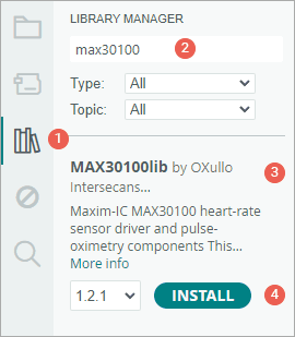
- First open your Arduino IDE program. Then click on the Library Manager icon on the left sidebar.
- Type “max30100” in the search box to filter your results.
- Look for the MAX30100lib Library by OXullo Intersecans.
- Click the Install button to add it to your Arduino IDE.
Example 1 – Measuring Heart-Rate (BPM) and Blood Oxygen level (SpO2)
In this example, we’re going to measure heart rate and blood oxygen level (SpO2) and show the results on the Serial Monitor. This example gives you a basic idea to see real-time biometric data using the MAX30100 sensor.
Warning:
This sensor uses light to detect your pulse. Many things can affect the readings, like movement or how you place your finger. So it’s great for learning and experimenting, but not reliable for medical use.
#include <Wire.h>
#include "MAX30100_PulseOximeter.h"
#define REPORTING_PERIOD_MS 1000
// Create a PulseOximeter object
PulseOximeter pox;
// Time at which the last beat occurred
uint32_t tsLastReport = 0;
// Callback routine is executed when a pulse is detected
void onBeatDetected() {
Serial.println("Beat!");
}
void setup() {
Serial.begin(9600);
Serial.print("Initializing pulse oximeter..");
// Initialize sensor
if (!pox.begin()) {
Serial.println("FAILED");
for (;;)
;
} else {
Serial.println("SUCCESS");
}
// Configure sensor to use 7.6mA for LED drive
pox.setIRLedCurrent(MAX30100_LED_CURR_7_6MA);
// Register a callback routine
pox.setOnBeatDetectedCallback(onBeatDetected);
}
void loop() {
// Read from the sensor
pox.update();
// Grab the updated heart rate and SpO2 levels
if (millis() - tsLastReport > REPORTING_PERIOD_MS) {
Serial.print("Heart rate:");
Serial.print(pox.getHeartRate());
Serial.print("bpm / SpO2:");
Serial.print(pox.getSpO2());
Serial.println("%");
tsLastReport = millis();
}
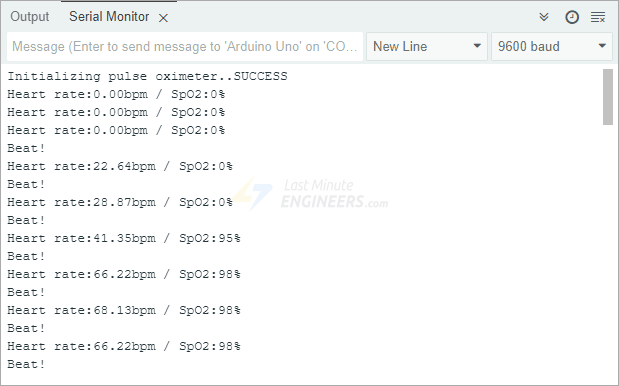
}After uploading the sketch to your Arduino, place your finger gently on the sensor and keep it as still as possible. Wait a few seconds while it collects data. Soon, you’ll see your heart rate and SpO2 reading appear on the Serial Monitor.
Code Explanation:
We begin by including two important libraries: Wire.h is used for I2C communication between the Arduino and the MAX30100 sensor. MAX30100_PulseOximeter.h is a library that helps us interact with the sensor easily.
#include <Wire.h>
#include "MAX30100_PulseOximeter.h"
Next, we define a constant named REPORTING_PERIOD_MS. This sets how often the heart rate and SpO2 readings will be shown on the Serial Monitor. In this case, it’s set to 1000 milliseconds, which means we’ll see updates once every second.
#define REPORTING_PERIOD_MS 1000Then, we create an object called pox, which will handle all the pulse oximeter functions. We also make a variable called tsLastReport, which stores the time of the last reading. This helps us know when one second has passed so we can print new data.
// Create a PulseOximeter object
PulseOximeter pox;

// Time at which the last beat occurred
uint32_t tsLastReport = 0;
We also set up a callback routine. This function gets triggered every time the sensor detects a heartbeat. In this example, it simply prints “Beat!” to the Serial Monitor. However, you can customize this function if you want; For example, you could make an LED blink.
void onBeatDetected() {
  Serial.println("Beat!");
}
Inside the setup() function, we first initiate the serial communication, and then try to connect to the sensor by calling pox.begin(). If it works, we print “SUCCESS.” If it doesn’t, we print “FAILED” and stop the program. This helps us quickly see whether the sensor is working or not.
if (!pox.begin()) {
  Serial.println("FAILED");
  for (;;)
    ;
} else {
  Serial.println("SUCCESS");
}
After that, we adjust the brightness of the infrared LED using the function setIRLedCurrent(). The infrared light is what shines through your finger to detect blood flow. In this example, we set the current to 7.6 mA-not too bright, not too dim.
pox.setIRLedCurrent(MAX30100_LED_CURR_7_6MA);This value is chosen because it works well in most situations. By default, the library sets the LED current to 50 mA, which is often too high and can make the sensor fail when starting up.
Here are some of the preset current values you can choose from. The options range from completely off (0mA) to very bright (50mA):
- MAX30100_LED_CURR_0MA
- MAX30100_LED_CURR_4_4MA
- MAX30100_LED_CURR_7_6MA
- MAX30100_LED_CURR_11MA
- MAX30100_LED_CURR_14_2MA
- MAX30100_LED_CURR_17_4MA
- MAX30100_LED_CURR_20_8MA
- MAX30100_LED_CURR_24MA
- MAX30100_LED_CURR_27_1MA
- MAX30100_LED_CURR_30_6MA
- MAX30100_LED_CURR_33_8MA
- MAX30100_LED_CURR_37MA
- MAX30100_LED_CURR_40_2MA
- MAX30100_LED_CURR_43_6MA
- MAX30100_LED_CURR_46_8MA
- MAX30100_LED_CURR_50MA
Remember: A higher current makes the LED shine brighter and reach deeper into your skin, but it also uses more power. Try different values to see what works best for your setup.
Finally, we connect our onBeatDetected function to the sensor using setOnBeatDetectedCallback(). This makes the function run automatically each time a pulse is detected.
pox.setOnBeatDetectedCallback(onBeatDetected);In the loop() function, we first call pox.update(). This is very important—it tells the sensor to check for new data and keep the heart rate and SpO2 readings up to date by reading from its internal FIFO buffer.
pox.update();Next, we check whether one full second has passed since the last time we printed the heart rate and SpO2 values. Instead of using delay() (which would pause the whole program), we use the millis() function. millis() keeps track of time in the background, so the rest of your program keeps running smoothly.
If a second has passed, we print the heart rate and SpO2 readings to the Serial Monitor. Then we update tsLastReport with the current time, so the next update happens after another second.
if (millis() - tsLastReport > REPORTING_PERIOD_MS) {
  Serial.print("Heart rate:");
  Serial.print(pox.getHeartRate());
  Serial.print("bpm / SpO2:");
  Serial.print(pox.getSpO2());
  Serial.println("%");

  tsLastReport = millis();
}
Having Trouble Seeing Your Heartbeat?
If your sensor isn’t picking up your heartbeat correctly, don’t worry! Here are some easy fixes to try:
- Don’t press too hard on the sensor. If you squeeze your finger too much, it stops blood from flowing properly.
- Don’t press too lightly either. That can let in extra light and cause a noisy signal.
- Try to find a “just right” pressure—like holding a coin gently between your fingers.
- Try using a rubber band or some tape to hold your finger steadily on the sensor.
- Test other body parts with thin skin and lots of blood flow, like your earlobe or lower lip.
Example 2 – Reading Red & IR Light Values
The second example shows you how to read the raw raw infrared (IR) and red light values from the sensor.
#include <Wire.h>
#include "MAX30100_PulseOximeter.h"
// Create a MAX30100 object
MAX30100 sensor;
void setup() {
Serial.begin(9600);
Serial.print("Initializing MAX30100..");
// Initialize sensor
if (!sensor.begin()) {
Serial.println("FAILED");
for (;;)
;
} else {
Serial.println("SUCCESS");
}
// Configure sensor
configureMax30100();
}
void loop() {
uint16_t ir, red;
sensor.update();
while (sensor.getRawValues(&ir, &red)) {
Serial.print("R[");
Serial.print(red);
Serial.print("] IR[");
Serial.print(ir);
Serial.println("]");
}
}
void configureMax30100() {
sensor.setMode(MAX30100_MODE_SPO2_HR);
sensor.setLedsCurrent(MAX30100_LED_CURR_50MA, MAX30100_LED_CURR_27_1MA);
sensor.setLedsPulseWidth(MAX30100_SPC_PW_1600US_16BITS);
sensor.setSamplingRate(MAX30100_SAMPRATE_100HZ);
sensor.setHighresModeEnabled(true);
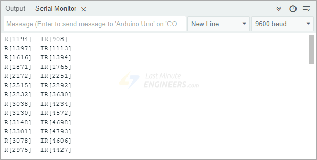
}After you upload the code to your Arduino, open the Serial Monitor. Point the sensor upward and move your hand over it. You’ll notice the numbers change as your hand reflects different amounts of light back to the sensor.
Visualizing the Data
Looking at just numbers can be confusing. A better way to understand what’s happening is to see the data as a graph using the Arduino Serial Plotter.
To do this, replace the while() loop in your sketch with the version below:
while (sensor.getRawValues(&ir, &red)) {
Serial.print(red);
Serial.print(", ");
Serial.println(ir);
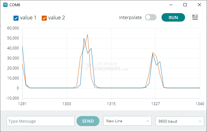
}In the Arduino IDE, choose Tools > Serial Plotter. When you wave your hand over the sensor, you’ll see two lines on the graph changing – one for red light and one for infrared light. This graph makes it much easier to see how the sensor responds to your hand movements.
Example 3 – Reading Temperature
As mentioned earlier, the MAX30100 has a built-in temperature sensor that measures the chip’s internal temperature (die temperature). While this sensor mainly helps adjust (or calibrate) heart rate and SpO2 readings for temperature changes, it also works well as a quick thermometer.
This example prints the temperature in both Celsius and Fahrenheit.
#include <Wire.h>
#include "MAX30100_PulseOximeter.h"

#define REPORTING_PERIOD_MS 1000

// Create a MAX30100 object
MAX30100 sensor;

// Time when the last reading was taken
uint32_t tsLastReading = 0;

void setup() {
  Serial.begin(9600);

  Serial.print("Initializing MAX30100..");

  // Initialize sensor
  if (!sensor.begin()) {
    Serial.println("FAILED");
    for (;;)
      ;
  } else {
    Serial.println("SUCCESS");
  }

  // Configure sensor
  configureMax30100();
}

void loop() {
  sensor.update();

  if (millis() - tsLastReading > REPORTING_PERIOD_MS) {
    sensor.startTemperatureSampling();
    if (sensor.isTemperatureReady()) {
      float temp = sensor.retrieveTemperature();
      Serial.print("Temperature = ");
      Serial.print(temp);
      Serial.print("*C | ");
      Serial.print((temp * 9.0) / 5.0 + 32.0);  //print the temperature in Fahrenheit
      Serial.println("*F");
    }
    tsLastReading = millis();
  }
}

void configureMax30100() {
  sensor.setMode(MAX30100_MODE_SPO2_HR);
  sensor.setLedsCurrent(MAX30100_LED_CURR_50MA, MAX30100_LED_CURR_27_1MA);
  sensor.setLedsPulseWidth(MAX30100_SPC_PW_1600US_16BITS);
  sensor.setSamplingRate(MAX30100_SAMPRATE_100HZ);
  sensor.setHighresModeEnabled(true);
}
Once the sketch is running, try placing your finger on the sensor or blowing gently across it. You should see the temperature rise slightly.

Example 4 – Presence Detection
In this final example, you’ll learn how to use the MAX30100 as a proximity or motion sensor.
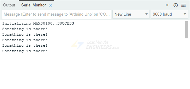
Here’s how it works: The sketch takes several readings at the beginning (during setup) and averages them to set a baseline. After that, it continuously checks for any sudden changes from this baseline. When something moves over the sensor—like your hand—it will print: “Something is there!”
#include <Wire.h>
#include "MAX30100_PulseOximeter.h"

#define REPORTING_PERIOD_MS 1000

int lastOccurrence = LOW;

// Create a MAX30100 object
MAX30100 sensor;

uint16_t ir, red;
uint16_t avg_ir = 0, avg_red = 0;

void setup() {
  Serial.begin(9600);

  Serial.print("Initializing MAX30100..");

  // Initialize sensor
  if (!sensor.begin()) {
    Serial.println("FAILED");
    for (;;)
      ;
  } else {
    Serial.println("SUCCESS");
  }

  configureMax30100();

  takeSampleReadings();
}

void loop() {
  sensor.update();

  while (sensor.getRawValues(&ir, &red)) {
    if (ir > 10 * avg_ir && red > 10 * avg_red) {
      if (lastOccurrence == LOW) {
        Serial.println("Something is there!");
        lastOccurrence = HIGH;
      }
    } else {
      lastOccurrence = LOW;
    }
  }
}

void configureMax30100() {
  sensor.setMode(MAX30100_MODE_SPO2_HR);
  sensor.setLedsCurrent(MAX30100_LED_CURR_50MA, MAX30100_LED_CURR_27_1MA);
  sensor.setLedsPulseWidth(MAX30100_SPC_PW_1600US_16BITS);
  sensor.setSamplingRate(MAX30100_SAMPRATE_100HZ);
  sensor.setHighresModeEnabled(true);
}

void takeSampleReadings() {
  delay(50);
  for (int i = 0; i <= 9; i++) {
    sensor.update();
    sensor.getRawValues(&ir, &red);
    avg_ir += ir;
    avg_red += red;
    delay(50);
  }
  avg_ir /= 10;
  avg_red /= 10;
}
Try uploading this sketch and swiping your hand over the sensor. Watch the Serial Monitor for the “Something is there!” message. You can also test how far away your hand can be while still being detected.
The MAX30100 is incredibly sensitive—it can detect tiny movements because it can read up to 65,536 different levels (16 bits) of light. That’s a lot of precision for detecting nearby objects!