
Imagine being able to monitor your home from anywhere, control your garden’s sprinklers with just a missed call, or get a text message right away when someone enters your house—all without needing an expensive security system. With the SIM800L GSM/GPRS module, you can turn these ideas into reality.
The SIM800L module is a tiny GSM modem that adds cellular connectivity to your Arduino projects. Just like your mobile phone, it can send text messages, make phone calls, and even connect to the internet using GPRS. Whether you’re building a home automation system, an emergency alert device, or something you want to control from far away, this module is a game-changer.
In this tutorial, we’ll guide you step-by-step on how to connect the SIM800L module to an Arduino. You’ll learn how to properly set up and power the SIM800L so it works reliably. We’ll also show you how to use the module with your Arduino to send and receive text messages, and even how to make and answer phone calls using simple code and commands.
Once you have these skills, you’ll be ready to create your own cellular-connected projects, control things remotely, and make the most of GSM communication. Let’s dive in!
Hardware Overview
At the heart of the module is the SIM800L GSM chip, created by a company called Simcom. This special chip allows electronic projects to connect to cellular networks—the same networks your phone uses. With this connection, your projects can send text messages, make phone calls, or even browse the internet.
The SIM800L operates on a voltage range of 3.4V to 4.4V, which means you can power it directly using a LiPo battery. This is really helpful for projects where you don’t have much space and need to be energy efficient.

The module connects to a microcontroller (like an Arduino) through UART. It supports a wide range of baud rates, from 1200 bps to 115200 bps, and it even has an automatic baud rate detection feature. This makes it flexible and easy to set up in different projects.
For the module to connect to a cellular network, it needs an antenna. Usually, the module comes with a small helical antenna that you can solder directly onto the board. However, if you want to place the antenna away from the module—perhaps to get better reception—there’s also a special connector called a U.FL connector. This allows you to attach an external antenna using a cable.

On the back of the module, you’ll find a slot for inserting a SIM card. Any 2G Micro SIM card will work fine with this module. If you’re not sure how to insert the SIM card correctly, look for a small engraving near the slot that shows the right way to put it in.
Features
Despite being very small—only about 1 square inch in size (roughly the size of a postage stamp)—the SIM800L module offers several powerful features. :
- Supports Quad-band: GSM850, EGSM900, DCS1800 and PCS1900
- Connect onto any global GSM network with any 2G SIM
- Make and receive voice calls using an external 8Ω speaker & electret microphone
- Send and receive SMS messages
- Send and receive GPRS data (TCP/IP, HTTP, etc.)
- Scan and receive FM radio broadcasts
- Transmit Power:
- Class 4 (2W) for GSM850
- Class 1 (1W) for DCS1800
- Serial-based AT Command Set
- FL connectors for cell antennae
- Accepts Micro SIM Card
LED Status Indicators
The SIM800L module has an LED that shows you the status of your cellular network connection. The LED will blink at different rates depending on what the module is doing:

Blink every 1s
The chip is running but hasn’t connected to the cellular network yet.

Blink every 2s
The GPRS data connection you requested is active and working.

Blink every 3s
The module has successfully connected to a cellular network and is ready to send/receive text messages and phone calls.
These blinking patterns help you troubleshoot your project and know when your module is working correctly.
Choosing an Antenna
The SIM800L module needs an external antenna to connect to the cellular network, and picking the right antenna is crucial for good performance. You have two main choices:
The first option is a small helical antenna. This antenna usually comes with the module and can be soldered directly onto the circuit board. It’s perfect when you don’t have much space for your project. However, you might struggle to get a good connection, especially if your project is inside a building where cell signals are weaker.

The second option is a 3dBi GSM antenna with a U.FL to SMA adapter. You can find these online for under $3. This antenna snaps into the small U.FL connector located in the top-left corner of the module. This type of antenna works much better than the helical one. You can even place your module inside a metal box as long as the antenna itself sticks outside the box.

Power Consumption
Making sure the SIM800L module has enough power is one of the most important parts of getting it to work properly.
The SIM800L can use quite a bit of power depending on what it’s doing. For example, it needs about 216mA when making a phone call and around 80mA during regular network communications. But during certain moments, like when it’s transmitting data in short bursts, it might suddenly need as much as 2A of current! If your power supply can’t provide this much power when needed, the module will keep restarting or simply not work correctly.
This chart from the datasheet shows how much power the module uses in different situations.
| Modes | Frequency | Current Consumption |
| Power down | 60 uA | |
| Sleep mode | 1 mA | |
| Stand by | 18 mA | |
| Call | GSM850 | 199 mA |
| EGSM900 | 216 mA | |
| DCS1800 | 146 mA | |
| PCS1900 | 131 mA | |
| GPRS | 453 mA | |
| Transmission burst | 2 A |
Selecting a Power Supply
The SIM800L module doesn’t have its own voltage regulator built in. This means you need to provide power that’s between 3.4V and 4.4V (with 4.0V being ideal). More importantly, your power supply must be able to handle those sudden 2A surges of current. If it can’t, the chip will reset whenever it needs more power.
Here are two good options for powering your SIM800L:
Li-Po Battery
A Li-Po battery is an excellent choice because its voltage naturally falls between 3.7V and 4.2V, which is perfect for the SIM800L. Any Li-Po battery with a capacity of 1200 mAh or higher should work well. These batteries can handle those sudden current spikes up to 2A while keeping a stable voltage.

DC-DC Buck Converter
Another good option is using a 2A-rated DC-DC buck converter, such as the LM2596, with the output voltage set to 4.0V (the ideal voltage for the module). Unlike simple voltage regulators, these converters waste less energy and provide a stable power supply to the module even during those high-demand moments.

SIM800L GSM Module Pinout
The SIM800L module has a total of 12 pins, each with a specific function. Let’s explore what each pin does so you can use this module correctly in your projects.

NET is where you connect the helical antenna that comes with your module.
VCC is the power supply pin. The SIM800L needs between 3.4V and 4.4V to work properly. This is important to remember because connecting it to an Arduino’s 5V output could damage your module. Even the Arduino’s 3.3V output isn’t enough to power it correctly! Instead, use a Li-Po battery or a DC-DC buck converter to get the right voltage.
RST (Reset) is used to restart the module. If your SIM800L gets stuck or starts acting strangely, you can pull this pin LOW for about 100 ms to perform a hard reset.
RxD (Receiver) receives commands that you send to the module. This pin has a cool feature called “auto-baud detection,” which means the speed at which you send your first “AT” command after resetting will set the speed for all future communication.
TxD (Transmitter) sends data from the module back to your microcontroller.
GND is simply the ground pin, which you need to connect to the ground of your circuit.
RING pin is the Ring Indicator. This is basically the ‘interrupt-out’ pin from the module. By default, this pin stays HIGH, but it can be configured to go LOW whenever a phone call or text message is received. This makes it useful for triggering alerts or notifications in your project.
DTR pin controls the sleep mode of the module. If you pull this pin HIGH, the module will enter sleep mode, which disables serial communication to save power. To wake it up, pull this pin LOW for about 50 ms.
MIC± are used for connecting an external microphone. These are differential microphone inputs, meaning you can directly attach an electret microphone to these two pins. This allows your module to capture audio for phone calls.
SPK± are used for connecting a speaker. Like the microphone pins, these are differential speaker interfaces. This means you can directly connect a small speaker to these pins for audio output during calls.
Wiring a SIM800L GSM Module to an Arduino
Now that you’re familiar with the SIM800L module, it’s time to connect it to an Arduino and start using it!
First, attach the antenna to the module and insert a micro SIM card into the SIM card slot.
As you know, the SIM800L module uses UART for communication. On an Arduino UNO, you can normally connect devices to pins 0 and 1, which are designed for this type of communication. However, there’s a problem – these same pins are also used when you connect your Arduino to your computer (like when uploading code or viewing messages in the serial monitor).
Since the Arduino Uno only has one built-in UART connection, we need to create a second one for our SIM800L module. We can do this using the SoftwareSerial library, which lets us turn regular digital pins into UART communication pins. For our project, we’ll use pins 2 and 3.
Making the Connections
So, connect the Tx (transmit) pin of the SIM800L to digital pin #3 on the Arduino.
But for the Rx (receive) pin, we need to be careful. The Arduino Uno works with 5V signals, but the SIM800L module works with 3.3V signals. If we connect them directly, we might damage the SIM800L.
To solve this problem, we’ll use a simple voltage divider made of resistors: Connect a 10KΩ resistor between the Arduino’s #2 pin and the SIM800L’s Rx pin. And connect a 20KΩ resistor between the SIM800L’s Rx pin and GND (ground). This setup safely reduces the 5V signal from the Arduino to about 3.3V that the SIM800L can handle.
The final step is connecting power to the module. Here are two ways to do this:
Option 1: Using a Battery
In this setup, a 1200mAh Li-Po battery powers the SIM800L module.

Option 2: Using a Voltage Converter
In this setup, an LM2596 DC-DC buck converter provides the correct voltage.

Warnings:
- Be very careful when connecting and disconnecting the power supply: Always connect GND (ground) before connecting VCC (power). And when disconnecting, remove VCC first, then GND. If you accidentally disconnect GND first, the module might try to use the low-voltage serial pins as ground instead, which could damage your SIM800L module.
- Make sure your circuit and Arduino share a common ground connection.
Arduino Code – Testing AT Commands
Let’s begin by testing AT commands with our SIM800L module. These commands help us communicate with the module and check if it is working correctly. To do this, we will use the Serial Monitor in the Arduino IDE.
Before diving into the details of the code, first, connect your Arduino to your computer, then compile and upload the provided code. Once done, open the Serial Monitor and make sure the “Both NL and CR” option is selected.
#include <SoftwareSerial.h>
//Create software serial object to communicate with SIM800L
SoftwareSerial mySerial(3, 2); //SIM800L Tx & Rx is connected to Arduino #3 & #2
void setup() {
//Begin serial communication with Arduino and Arduino IDE (Serial Monitor)
Serial.begin(9600);
//Begin serial communication with Arduino and SIM800L
mySerial.begin(9600);
Serial.println("Initializing...");
delay(1000);
mySerial.println("AT"); //Once the handshake test is successful, it will back to OK
updateSerial();
mySerial.println("AT+CSQ"); //Signal quality test, value range is 0-31 , 31 is the best
updateSerial();
mySerial.println("AT+CCID"); //Read SIM information to confirm whether the SIM is plugged
updateSerial();
mySerial.println("AT+CREG?"); //Check whether it has registered in the network
updateSerial();
}
void loop() {
updateSerial();
}
void updateSerial() {
delay(500);
while (Serial.available()) {
mySerial.write(Serial.read()); //Forward what Serial received to Software Serial Port
}
while (mySerial.available()) {
Serial.write(mySerial.read()); //Forward what Software Serial received to Serial Port
}
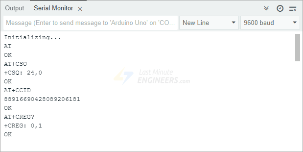
}After uploading the code, open the Serial Monitor at 9600 baud rate. You should see the below output on the serial monitor.
Code Explanation:
We start by including the SoftwareSerial library, which allows us to use digital pins as additional serial communication ports. Since the SIM800L module communicates over a serial connection, we need to define which Arduino pins will handle this communication. Here, we connect: Tx (Transmit) of SIM800L to pin 3 of Arduino and Rx (Receive) of SIM800L to pin 2 of Arduino.
#include <SoftwareSerial.h>

//Create software serial object to communicate with SIM800L
SoftwareSerial mySerial(3, 2); //SIM800L Tx & Rx is connected to Arduino #3 & #2
Next, in the setup() function, we establish serial communication. We first set up the connection between the Arduino and the Serial Monitor (your computer) at a speed of 9600 baud.
We also set up the communication between Arduino and the SIM800L module at the same speed.
//Begin serial communication with Arduino and Arduino IDE (Serial Monitor)
Serial.begin(9600);

//Begin serial communication with Arduino and SIM800L
mySerial.begin(9600);
Once everything is initialized, we send below AT commands to check if the module is responding.
AT – This is the first test command. If the module responds with ‘OK,’ it means everything is working correctly. This command also helps with auto baud rate detection, allowing the module to automatically adjust to the correct communication speed.
AT+CSQ – This command checks the signal strength. It will return a number between 0 and 31. The higher the number, the better the signal. If the number is too low, your module may have a weak connection due to a bad antenna or poor location.
AT+CCID – This command verifies if a SIM card is inserted and will display its unique identification number.
AT+CREG? – This checks whether the module is registered to a mobile network. If it returns 1, you are connected to your home network. If it returns 5, you are on roaming. If it returns any other number, the module is not connected to any network.
mySerial.println("AT");       //Once the handshake test is successful, it will back to OK
updateSerial();
mySerial.println("AT+CSQ");   //Signal quality test, value range is 0-31 , 31 is the best
updateSerial();
mySerial.println("AT+CCID");  //Read SIM information to confirm whether the SIM is plugged
updateSerial();
mySerial.println("AT+CREG?"); //Check whether it has registered in the network
updateSerial();
In the loop() function, we call a custom function called updateSerial(). This function constantly listens for commands you type into the Serial Monitor and sends them to the SIM800L module. It also listens for any response from the SIM800L module and prints it to the Serial Monitor so you can see what the module is saying back.
void updateSerial() {
  delay(500);
  while (Serial.available()) {
    mySerial.write(Serial.read());  //Forward what Serial received to Software Serial Port
  }
  while (mySerial.available()) {
    Serial.write(mySerial.read());  //Forward what Software Serial received to Serial Port
  }
}
Try Sending Different AT Commands
Once your module is responding correctly, you can manually type and send different AT commands through the Serial Monitor to get more information. Try these:
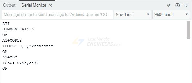
ATI – This command returns the module name and firmware version.
AT+COPS? – This command shows which mobile network you are currently connected to.
AT+COPS=? – This command displays all available networks in your area.
AT+CBC – This command checks the battery status of the SIM800L module. It will show the battery percentage and voltage level.
Arduino Code – Sending a Text Message
Now that we have tested basic AT commands, let’s move on to something more exciting—sending a text message to any phone number using the SIM800L module.
Before you upload the code, you need to enter the phone number where you want the text message to be sent. Look for the section in the code that contains ZZxxxxxxxxxx and replace it with the correct details:
- ZZ should be your country code (for example, 1 for the USA, 91 for India).
- xxxxxxxxxx should be the 10-digit phone number where you want to send the message.
Once you have entered the correct phone number, you can compile and upload the code to your Arduino.
#include <SoftwareSerial.h>
//Create software serial object to communicate with SIM800L
SoftwareSerial mySerial(3, 2); //SIM800L Tx & Rx is connected to Arduino #3 & #2
void setup() {
//Begin serial communication with Arduino and Arduino IDE (Serial Monitor)
Serial.begin(9600);
//Begin serial communication with Arduino and SIM800L
mySerial.begin(9600);
Serial.println("Initializing...");
delay(1000);
mySerial.println("AT"); //Once the handshake test is successful, it will back to OK
updateSerial();
mySerial.println("AT+CMGF=1"); // Configuring TEXT mode
updateSerial();
mySerial.println("AT+CMGS=\"+ZZxxxxxxxxxx\""); //change ZZ with country code and xxxxxxxxxxx with phone number to sms
updateSerial();
mySerial.print("Last Minute Engineers | lastminuteengineers.com"); //text content
updateSerial();
mySerial.write(26);
}
void loop() {
}
void updateSerial() {
delay(500);
while (Serial.available()) {
mySerial.write(Serial.read()); //Forward what Serial received to Software Serial Port
}
while (mySerial.available()) {
Serial.write(mySerial.read()); //Forward what Software Serial received to Serial Port
}
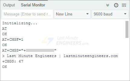
}Once you upload the code, open the Serial Monitor in the Arduino IDE and wait for the module to send the message. If everything is set up correctly, you should receive the text message on the specified phone number.

Code Explanation:
The sketch is very similar to the first one, except for the following AT commands used to send a text message to a specific number:
AT+CMGF=1 – This command sets the GSM modem to SMS TEXT Mode. By default, the modem uses PDU (Protocol Data Unit) mode, which is more complex, so we switch it to text mode to make it easier to send messages.
AT+CMGS=+ZZxxxxxxxxxx – The AT+CMGS command, followed by the phone number, tells the SIM800L module that we want to send a text message to that specific number. After sending this AT command, any text message you type, followed by the ‘Ctrl+Z’ character, will be treated as a text message. The ‘Ctrl+Z’ character (ASCII code 26) tells the module that you have finished typing the message, and it should send the message immediately.
mySerial.println("AT+CMGF=1"); // Configuring TEXT mode
updateSerial();
mySerial.println("AT+CMGS=\"+ZZxxxxxxxxxx\"");//change ZZ with country code and xxxxxxxxxxx with phone number to sms
updateSerial();
mySerial.print("Last Minute Engineers | lastminuteengineers.com"); //text content
updateSerial();
mySerial.write(26);
One important thing to note is that the loop() function is empty. This is because we only want to send the text message once when the Arduino starts up. If you want to send another text message, you simply need to press the RESET button on your Arduino, which will restart the program and send the message again.
Arduino Code – Reading a Text Message
Now, let’s program our Arduino to read incoming text messages. This can be incredibly useful in situations where you want to trigger an action based on a received text message. Imagine being able to turn on lights, start a fan, or even activate a sprinkler system just by sending a message from your phone.
#include <SoftwareSerial.h>

//Create software serial object to communicate with SIM800L
SoftwareSerial mySerial(3, 2);  //SIM800L Tx & Rx is connected to Arduino #3 & #2

void setup() {
  //Begin serial communication with Arduino and Arduino IDE (Serial Monitor)
  Serial.begin(9600);

  //Begin serial communication with Arduino and SIM800L
  mySerial.begin(9600);

  Serial.println("Initializing...");
  delay(1000);

  mySerial.println("AT");  //Once the handshake test is successful, it will back to OK
  updateSerial();

  mySerial.println("AT+CMGF=1");  // Configuring TEXT mode
  updateSerial();
  mySerial.println("AT+CNMI=1,2,0,0,0");  // Decides how newly arrived SMS messages should be handled
  updateSerial();
}

void loop() {
  updateSerial();
}

void updateSerial() {
  delay(500);
  while (Serial.available()) {
    mySerial.write(Serial.read());  //Forward what Serial received to Software Serial Port
  }
  while (mySerial.available()) {
    Serial.write(mySerial.read());  //Forward what Software Serial received to Serial Port
  }
}
Once you upload the code, open the Serial Monitor and send a text message to the SIM800L module from your phone. You should see the incoming message displayed on the screen.


As you can see the response starts with +CMT: followed by details in a comma-separated format. The first field is the sender’s phone number, the second field is the sender’s name (if available), the third field is the timestamp, and the last field is the actual text message.
Code Explanation:
The sketch is very similar to the first one, except for the following AT commands used to read a received text message:
AT+CMGF=1 – This command sets the GSM modem to SMS TEXT Mode. By default, the module uses PDU mode, which is harder to read, so we change it to text mode to make things easier.
AT+CNMI=1,2,0,0,0 – This command controls how incoming text messages are handled. It allows you to tell the SIM800L module whether to forward incoming text messages directly to the Serial Monitor or to save them in the message storage. If the messages are saved, the module will then notify the computer about their locations in the storage.
mySerial.println("AT+CMGF=1"); // Configuring TEXT mode
updateSerial();
mySerial.println("AT+CNMI=1,2,0,0,0"); // Decides how newly arrived SMS messages should be handled
updateSerial();
Note that unlike the previous sketch, this time the loop() function is not empty. Since we need to continuously check for new messages, the code keeps listening for incoming messages in an endless loop, ensuring that any new message is immediately displayed on the Serial Monitor.
Handling Longer Messages
If you notice that long messages are getting cut off or missing some characters, don’t worry—it’s not a problem with your code. The issue happens because the “Software Serial Receive Buffer” is too small. By default, it is set to 64 bytes, which means it can only store a limited amount of data before discarding the rest.
The solution is simple: increase the SoftwareSerial buffer size to 256 bytes. If you are using a Windows PC, follow these steps:
Go to C:\Program Files (x86)\Arduino\hardware\arduino\avr\libraries\SoftwareSerial\src and open the file SoftwareSerial.h in a text editor. Look for the line that defines the buffer size:
// RX buffer size
#define _SS_MAX_RX_BUFF 64
Change the value from 64 to 256:
// RX buffer size
#define _SS_MAX_RX_BUFF 256
Save the file and re-upload the code to your Arduino. Now, your Arduino should be able to receive and display longer messages without losing any characters.

Arduino Code – Making a Call
Now, let’s program our Arduino to make a phone call. This can be incredibly useful in emergency situations where the Arduino needs to automatically dial a number for help. Imagine scenarios like a fire alarm detecting high temperatures or a security system detecting an intruder—in such cases, the Arduino can make a call to alert someone immediately.
Before running the code, you need to enter the phone number that the Arduino should call. Look for the section in the code that contains ZZxxxxxxxxxx and replace it with the correct details:
- ZZ is the country code (for example, 1 for the USA, 91 for India).
- xxxxxxxxxx is the 10-digit phone number you want to call.
Once you’ve updated the phone number, upload the code to your Arduino.
#include <SoftwareSerial.h>
//Create software serial object to communicate with SIM800L
SoftwareSerial mySerial(3, 2); //SIM800L Tx & Rx is connected to Arduino #3 & #2
void setup() {
//Begin serial communication with Arduino and Arduino IDE (Serial Monitor)
Serial.begin(9600);
//Begin serial communication with Arduino and SIM800L
mySerial.begin(9600);
Serial.println("Initializing...");
delay(1000);
mySerial.println("AT"); //Once the handshake test is successful, i t will back to OK
updateSerial();
mySerial.println("ATD+ +ZZxxxxxxxxxx;"); // change ZZ with country code and xxxxxxxxxxx with phone number to dial
updateSerial();
delay(20000); // wait for 20 seconds...
mySerial.println("ATH"); //hang up
updateSerial();
}
void loop() {
}
void updateSerial() {
delay(500);
while (Serial.available()) {
mySerial.write(Serial.read()); //Forward what Serial received to Software Serial Port
}
while (mySerial.available()) {
Serial.write(mySerial.read()); //Forward what Software Serial received to Serial Port
}
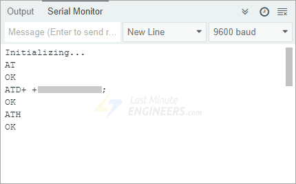
}Once the code is uploaded, the SIM800L module will automatically dial the specified phone number. If everything is working correctly, the recipient’s phone should start ringing.

Code Explanation:
The sketch is very similar to the first one, except for the following AT commands used to make a phone call.
ATD+ +ZZxxxxxxxxxx; – This command is used to dial a phone number. It is very important to include the semicolon (;) at the end of this command, as it tells the module to make a voice call instead of a data call. After sending this command, the SIM800L module starts calling the specified number.
ATH – This command tells the module to hang up and end the call.
mySerial.println("ATD+ +ZZxxxxxxxxxx;"); //  change ZZ with country code and xxxxxxxxxxx with phone number to dial
updateSerial();
delay(20000); // wait for 20 seconds...
mySerial.println("ATH"); //hang up
updateSerial();
The code waits for 20 seconds, giving enough time for the call to ring. After that, we send ATH, which tells the module to hang up and end the call. If you want to end the call sooner, you can reduce the delay. If you’d like the call to last longer, you can increase the delay time.
Since the call is only made once when the Arduino starts, the loop() function is empty. If you want to make another call, simply press the RESET button on the Arduino, which will restart the program and trigger the call again.
Arduino Code – Receiving a Call
Unlike making a call or sending a text message, no special code is required to receive an incoming call using the SIM800L module. The Arduino simply listens for incoming signals, and when a call is received, it is displayed on the Serial Monitor.
This can be incredibly useful in situations where you want your Arduino to detect calls from specific phone numbers and trigger an action, such as unlocking a door, turning on a light, or activating a security alarm.
#include <SoftwareSerial.h>
//Create software serial object to communicate with SIM800L
SoftwareSerial mySerial(3, 2); //SIM800L Tx & Rx is connected to Arduino #3 & #2
void setup() {
//Begin serial communication with Arduino and Arduino IDE (Serial Monitor)
Serial.begin(9600);
//Begin serial communication with Arduino and SIM800L
mySerial.begin(9600);
Serial.println("Initializing...");
}
void loop() {
updateSerial();
}
void updateSerial() {
delay(500);
while (Serial.available()) {
mySerial.write(Serial.read()); //Forward what Serial received to Software Serial Port
}
while (mySerial.available()) {
Serial.write(mySerial.read()); //Forward what Software Serial received to Serial Port
}
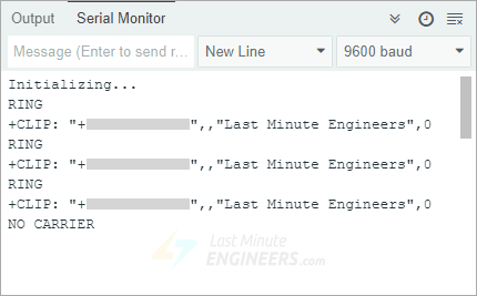
}Once you upload the code and open the Serial Monitor. The moment someone calls the module’s SIM card number, you will see the word “RING” appear on the Serial Monitor, followed by the caller’s phone number and caller ID.

Code Explanation:
The code is very simple because receiving a call does not require sending any AT commands to the module.
The loop() function continuously runs the updateSerial() function, which listens for data received from the SIM800L module. When a call comes in, the module automatically prints “RING”, followed by the caller’s phone number and other details. This way, you can see who is calling in real time.
The following AT commands can be used to answer or hang up a call:
ATA – This command is used to answer the call.
ATH – This command is used to immediately disconnect the call. When the call ends, you will see ‘NO CARRIER’ on the Serial Monitor, indicating that the call has been disconnected.