
Whether you’re building a digital clock, stopwatch, or simple counter, a 4-digit 7-segment display is often the perfect way to show numeric data in a clear and compact format. But if you’ve ever tried wiring up a bare 7-segment display to an Arduino, you know it can quickly eat up a dozen pins and turn your breadboard into a spaghetti mess of jumper wires. Thankfully, there’s a smarter way to do it.
Enter the TM1637 module — a tiny yet powerful driver chip that makes it easy to control a 4-digit 7-segment display using just two Arduino pins. That’s right: with only two data lines, you can control all four digits, along with colons and decimal points.
In this tutorial, we’ll walk you through how to hook up the TM1637 to your Arduino, load the right library, and start displaying numbers in no time.
Let’s dive in!
7-Segment Display Basics
A 7-segment display is made up of seven separate LEDs arranged in the shape of the number “8.” Each of these LEDs is called a segment.

The interesting thing about these displays is how they’re wired. Each segment has two electrical connection points, just like any regular LED. However, only one of these connection points extends out of the plastic casing as an individual pin that you can connect to. These pins are labeled with letters from ‘a’ to ‘g’—one letter for each segment. The other connection points are all wired together inside the plastic case to create a shared connection called the common pin (COM).
To light up the display, you can control each segment individually by setting its pin to HIGH or LOW, just like you would with any regular LED. By turning on different combinations of segments, you can create all the numbers from 0 to 9. With a little creativity, you can even display certain letters of the alphabet!

TM1637 Module Hardware Overview
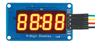
The TM1637 module combines a 0.36-inch 4-digit 7-segment display with the TM1637 LED driver chip made by Titan MicroElectronics. This cool combination lets you control all four digits using just two pins from your microcontroller.

This module is perfect for projects where you need to display numbers, like timers, counters, sensor readings, or temperatures. It even has a colon in the middle, which makes it great for clocks and time-related projects.
One of the best things about the TM1637 is that it handles refreshing the display on its own after you update it. This means your microcontroller is free to work on other important tasks instead of constantly refreshing the display.

The amount of power the module uses depends on how many segments are lit and the brightness level you set. When all segments are lit at maximum brightness, the module uses about 80 mA of current. You can save power by adjusting the display’s brightness to a lower level.
The TM1637 module works with a supply voltage between 3.3V and 5V. This makes it compatible with both 5V microcontrollers like the regular Arduino and 3.3V microcontrollers like the ESP32.
The module uses its own special two-wire communication protocol. While this isn’t a standard protocol like I2C, there are easy-to-use Arduino libraries available that hide all the complicated stuff and make it simple to communicate with the display.
Technical Specifications
Here are the specifications:
| Operating voltage | 3.3 – 5 VDC |
| Maximum Current Draw | 80mA |
| Reverse polarity protection | Yes |
| Display Size | 42 mm x 24 mm (1.65″ x .95″) |
| Display Height | 12 mm (0.47″) (typical) |
| Character Height | 9.14 mm (0.36″) |
For more detailed information about the TM1637 driver chip, please refer to the datasheet below.
TM1637 Module Pinout
The TM1637 module has only four pins, making it very simple to use. Here is the pinout:

CLK is the clock input pin.
DIO is the data input/output (I/O) pin.
VCC is the power supply pin. Connect it to a 3.3V to 5V power source.
GND is the ground pin.
Wiring the TM1637 Module with an Arduino
Connecting the TM1637 to an Arduino is very simple. Since the module only has four pins, you just need four wires: two for power and two for communication.
Start by connecting the VCC pin of the module to the 5V output on the Arduino, and the GND pin to one of the Arduino’s ground (GND) pins. Then, connect the CLK pin to digital pin 3 on the Arduino, and the DIO pin to digital pin 4.
Here’s a quick reference table for the pin connections:
| TM1637 Module | Arduino | |
| VCC | 5V | |
| GND | GND | |
| DIO | 4 | |
| CLK | 3 |
This diagram shows you exactly how to connect everything:

The great thing about the TM1637 module is that it doesn’t need specific pins, so you can use different digital pins if you want. Just remember that if you use different pins, you’ll need to update the pin numbers in your Arduino code to match your wiring.
Library Installation
To communicate with the TM1637 chip, you will need to use a library. A great option is the TM1637Display library created by Avishay Orpaz. This library has many built-in functions that make controlling the display simple and straightforward.
To install the library,
- First open your Arduino IDE program. Then click on the Library Manager icon on the left sidebar.
- Type “tm1637” in the search box to filter your results.
- Look for the TM1637 library by Avishay Orpaz.
- Click the Install button to add it to your Arduino IDE.
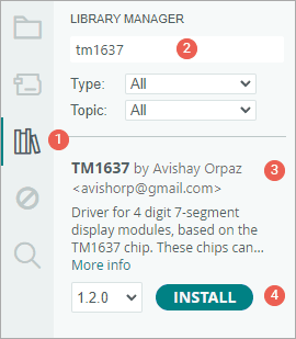
Once the library is installed, you’re all set and ready for programming!
Arduino Example 1 – Basic Test Program
The following is a basic test program that goes through a bunch of different routines. Give it a try; we’ll go over how the code works in a moment.
// Include the library
#include <TM1637Display.h>

// Define the connections pins
#define CLK 3
#define DIO 4

// Create a display object of type TM1637Display
TM1637Display display = TM1637Display(CLK, DIO);

// Create an array that turns all segments ON
const uint8_t allON[] = { 0xff, 0xff, 0xff, 0xff };

// Create an array that turns all segments OFF
const uint8_t allOFF[] = { 0x00, 0x00, 0x00, 0x00 };

// Create an array that sets individual segments per digit to display the word "dOnE"
const uint8_t done[] = {
  SEG_B | SEG_C | SEG_D | SEG_E | SEG_G,          // d
  SEG_A | SEG_B | SEG_C | SEG_D | SEG_E | SEG_F,  // O
  SEG_C | SEG_E | SEG_G,                          // n
  SEG_A | SEG_D | SEG_E | SEG_F | SEG_G           // E
};

// Create degree celsius symbol
const uint8_t celsius[] = {
  SEG_A | SEG_B | SEG_F | SEG_G,  // Degree symbol
  SEG_A | SEG_D | SEG_E | SEG_F   // C
};

void setup() {
  // Set the brightness to 5 (0=dimmest 7=brightest)
  display.setBrightness(5);

  // Set all segments ON
  display.setSegments(allON);
  delay(2000);
  display.clear();

  // Show counter 0-9
  int i;
  for (i = 0; i < 10; i++) {
    display.showNumberDec(i);
    delay(50);
  }
  delay(2000);
  display.clear();

  display.showNumberDec(-12);  // Prints _-12
  delay(2000);
  display.clear();

  display.showNumberDec(-999);  // Prints -999
  delay(2000);
  display.clear();

  display.showNumberDec(31, false);  // Prints __31
  delay(2000);
  display.clear();

  display.showNumberDec(31, true);  // Prints 0031
  delay(2000);
  display.clear();

  display.showNumberDec(14, false, 2, 1);  // Prints _14_
  delay(2000);
  display.clear();

  display.showNumberDec(-5, false, 2, 1);  // Prints _-5_
  delay(2000);
  display.clear();

  // Prints 12:34
  display.showNumberDecEx(1234, 0b01000000, false, 4, 0);
  delay(2000);
  display.clear();

  // Prints 15°C
  int temperature = 15;
  display.showNumberDec(temperature, false, 2, 0);
  display.setSegments(celsius, 2, 2);
  delay(2000);
  display.clear();

  // Prints dOnE
  display.setSegments(done);
}

void loop() {
}
Once you upload the sketch to your Arduino, you should see:
Code Explanation:
We begin by including the TM1637 library, and telling the program which two Arduino pins are connected to the display module — one for the clock (CLK) and the other for the data input/output (DIO).
#include <TM1637Display.h>

#define CLK 3
#define DIO 4
Next, we create a display object from the TM1637Display class. This object lets us send commands to the TM1637. When we create the object, we have to tell it which two pins we are using.
TM1637Display display = TM1637Display(CLK, DIO);The TM1637 library lets us control each segment of the display individually. This is how we can show numbers, letters, and even a few simple symbols on the screen.
To demonstrate this, we prepare four arrays. The first array is for turning on all the segments. The second is for turning all the segments off. The third array will make the display show the word “dOnE,” and the fourth will show a degree symbol (°) followed by the letter C. We use a function called setSegments() to send these arrays to the display and show them.
There are two ways to define these arrays.
1. Using hexadecimal numbers: When you use this method, you create the hex number following a specific order for the segments: (dot) G F E D C B A. Each letter stands for one segment on the display, and each segment can either be on (1) or off (0).
For example, the hex number 0xFF (which is 11111111 in binary) turns on all the segments, including the dot. On the other hand, 0x00 (which is 00000000 in binary) turns off all the segments.
If you want to display the letter “C,” you would use the hex number 0x39. In binary, that’s 00111001. This pattern turns on segments A, D, E, and F, while leaving the others off.
// Create an array that turns all segments ON
const uint8_t allON[] = {0xff, 0xff, 0xff, 0xff};

// Create an array that turns all segments OFF
const uint8_t allOFF[] = {0x00, 0x00, 0x00, 0x00};
2. Using segment names: The second way to create these arrays is even simpler. We can just list the segment names we want to turn on, using names like SEG_A, SEG_B, SEG_C, and so on.
// Create an array that sets individual segments per digit to display the word "dOnE"
const uint8_t done[] = {
  SEG_B | SEG_C | SEG_D | SEG_E | SEG_G,          // d
  SEG_A | SEG_B | SEG_C | SEG_D | SEG_E | SEG_F,  // O
  SEG_C | SEG_E | SEG_G,                          // n
  SEG_A | SEG_D | SEG_E | SEG_F | SEG_G           // E
};

// Create °C symbol
const uint8_t celsius[] = {
  SEG_A | SEG_B | SEG_F | SEG_G,  // °
  SEG_A | SEG_D | SEG_E | SEG_F   // C
};
In the setup() section of the code, we use several functions from the TM1637 library:
setBrightness(brightness,on)
This function controls the brightness of the display. You can choose any value between 0 (very dim) and 7 (very bright).
There’s also an optional second part you can add: if you pass false, it will turn off the display; if you pass true or leave it out, the display stays on. So when you write display.setBrightness(5), you are setting the brightness to a medium level. If you write display.setBrightness(5, false), you are actually turning the display off, even though you chose a brightness level.
setSegments(segments[],length,position)
This function lets you control individual segments of the display. We give it three pieces of information: the array that holds the information about which segments to light up, how many digits we want to update (from 0 to 4), and where the number should start on the display (position 0 is the leftmost digit, and position 3 is the rightmost).
Note that the second and third arguments are optional. If you want to update the entire display without worrying about length or position, you can just skip them. For example, when we want to display the word “dOnE,” we are lighting up all 4 digits starting from the leftmost position (position 0). So, we simply call the function like this:
// Prints dOnE
display.setSegments(done);
But sometimes we don’t want to update all four digits. For example, when we want to show the “°C” symbol, we only want to update the last two digits. In that case, we also tell the function how many digits (2) and from which position (2) to start.
// Prints __°C
display.setSegments(celsius, 2, 2);showNumberDec(number,leading_zeros,length,position)
Another very important function we use is showNumberDec(). This function is great for quickly displaying numbers. We just tell it which number we want to show, and it figures out which segments to light up. For example, if you want to count from 0 to 9, you can use a loop with showNumberDec() like this:
// Show counter 0-9
int i;
for (i = 0; i < 10; i++) {
  display.showNumberDec(i);
  delay(50);
}
You can also use this function to display negative numbers. It will automatically add the minus sign in the right place:
display.showNumberDec(-12);  // Prints _-12

display.showNumberDec(-999);  // Prints -999
The second argument controls whether or not you want to add leading zeros. If you set this to true, the display will add zeros in front to make the number fit all four digits. If you set it to false, it will just show the number as-is.
display.showNumberDec(31, false);  // Prints __31

display.showNumberDec(31, true);  // Prints 0031
The third and fourth arguments work the same way as before. They let you decide how many digits you want to update and where the number should start on the display. So, if you want the number to appear centered in the display, you would write:
display.showNumberDec(14, false, 2, 1);  // Prints _14_

display.showNumberDec(-5, false, 2, 1); // Prints _-5_showNumberDecEx(number,dots,leading_zeros,length,position)
This function is an extended version of showNumberDec(). The main difference is that the second argument now controls the dots or colons on the display, which is perfect for showing times or decimal numbers. To control these dots, you use a binary number that tells the display exactly which dots to turn on. Each position in the binary number corresponds to a specific dot on your display. For example:
If you have a display with dots between each digit, here’s how it works:
| Argument | Dots | Example |
| 0b10000000 | . | 1.234 |
| 0b01000000 | . | 12.34 |
| 0b00100000 | . | 123.4 |
| 0b11100000 | . . . | 1.2.3.4 |
Some TM1637 displays have a colon instead of dots. In this case:
| Argument | Dots | Example |
| 0b01000000 | : | 12:34 |
There are even displays that have both dots and a colon. On these displays:
| Argument | Dots | Example |
| 0b11100000 | . : . | 1.2:3.4 |
Let’s say you want to make a digital clock that shows “12:34”. You would use the function like this:
// Prints 12:34
display.showNumberDecEx(1234, 0b01000000, false, 4, 0);
First, you’d tell it to display the number 1234. Then, you’d use the binary code 0b01000000 to turn on the colon in the middle. The last few arguments tell the function not to add leading zeros, to update all four digits, and to start at the first position.
Since there’s nothing that needs to run repeatedly in this example, we leave the loop() function empty.
void loop() {
}
Arduino Example 2 – Digital Thermometer with TM1637 and DHT11/DHT22
The TM1637 module is perfect for displaying numerical values like temperature, humidity, voltage, or speed. In this example, we’ll use it to show temperature readings from a DHT11 sensor.
If you haven’t worked with DHTxx module before, you might want to check out this helpful tutorial:

Wiring
The wiring is similar to the first example, but we’re adding a DHT11 sensor to the setup.
Connect the VCC pin of the DHT11 sensor to the 5V pin on the Arduino and connect the GND pin to any GND pin on the Arduino. Connect the Data pin to digital pin #2 on the Arduino. You’ll also need to add a 10K pull-up resistor between the Data pin and the VCC pin. However, if you have a DHT11 on a breakout board, the resistor is already built in, so you can skip this step.

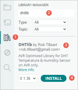
Library Installation
We’ll be using the DHTlib library for communicating with the DHT11, so make sure you install it first before proceeding.
To install the library:
- First open your Arduino IDE program. Then click on the Library Manager icon on the left sidebar.
- Type “dhtlib” in the search box to filter your results.
- Look for the “DHTlib” library created by Rob Tillaart.
- Click the Install button to add it to your Arduino IDE.
Arduino Code
The sketch below communicates with the DHT11 sensor and displays the temperature readings on the TM1637 display. The temperature will be shown in both Celsius and Fahrenheit, switching every two seconds.
// Include the libraries
#include <TM1637Display.h>
#include <dht.h>

// Define the connections pins
#define CLK 3
#define DIO 4
#define DHTPIN 2

// Create °C symbol
const uint8_t celsius[] = {
  SEG_A | SEG_B | SEG_F | SEG_G,  // Circle
  SEG_A | SEG_D | SEG_E | SEG_F   // C
};

// Create °F symbol
const uint8_t fahrenheit[] = {
  SEG_A | SEG_B | SEG_F | SEG_G,  // Circle
  SEG_A | SEG_E | SEG_F | SEG_G   // F
};

// Create display object of type TM1637Display
TM1637Display display = TM1637Display(CLK, DIO);

// Creates a DHT object
dht DHT;

void setup() {
  // Set the display brightness (0-7)
  display.setBrightness(5);

  // Clear the display
  display.clear();
}

void loop() {
  //Uncomment whatever type you're using!
  //DHT.read22(DHTPIN); // DHT22/AM2302
  DHT.read11(DHTPIN);  // DHT11

  int temperature_celsius = DHT.temperature;                              // Gets the values of the temperature
  int temperature_fahrenheit = (temperature_celsius * 9.0) / 5.0 + 32.0;  // Convert temperature to fahrenheit

  // Display the temperature in celsius format
  display.showNumberDec(temperature_celsius, false, 2, 0);
  display.setSegments(celsius, 2, 2);
  delay(2000);

  // Display the temperature in fahrenheit format
  display.showNumberDec(temperature_fahrenheit, false, 2, 0);
  display.setSegments(fahrenheit, 2, 2);
  delay(2000);
}
Once you upload the sketch to your Arduino, you should see:

Code Explanation
This sketch is similar to the previous one. However, there are a few key differences.
At the start of the code, along with including the TM1637Display library, we also include the DHT library to read temperature values from the sensor.
#include <DHT.h>Then, we define which Arduino pins are connected to the TM1637 display and which pin is connected to the DHT11 sensor.
#define CLK 3
#define DIO 4

#define DHTPIN 2
Next, we create two small arrays that store the segment patterns needed to display the “°C” and “°F” symbols on the TM1637.
// Create °C symbol
const uint8_t celsius[] = {
  SEG_A | SEG_B | SEG_F | SEG_G,  // Circle
  SEG_A | SEG_D | SEG_E | SEG_F   // C
};

// Create °F symbol
const uint8_t fahrenheit[] = {
  SEG_A | SEG_B | SEG_F | SEG_G,  // Circle
  SEG_A | SEG_E | SEG_F | SEG_G   // F
};
After that, we create an object for the display and another object for the DHT sensor.
TM1637Display display = TM1637Display(CLK, DIO);

dht DHT;
In the setup() section of the code, we set the brightness of the display to a medium level (5), which makes it easily readable without being too bright. We also clear the display to ensure it starts with a blank screen.
void setup() {
  // Set the display brightness (0-7)
  display.setBrightness(5);

  // Clear the display
  display.clear();
}
In the loop() section, we begin by reading the temperature data from the sensor. If you’re using a DHT11 sensor, use the read11() function. If you’re using a DHT22, use read22() instead. Only one of these should be active in your code—be sure to comment out the line for the sensor you’re not using and leave the correct one uncommented.
//Uncomment whatever type you're using!
//DHT.read22(DHTPIN); // DHT22/AM2302
DHT.read11(DHTPIN);  // DHT11
After reading the data, we retrieve the temperature in Celsius using the dot . notation from the DHT object and store it in a variable named temperature_celsius. We then calculate the Fahrenheit value using the formula (Celsius × 9 / 5) + 32 and store it in another variable named temperature_fahrenheit.
int temperature_celsius = DHT.temperature;                              // Gets the values of the temperature
int temperature_fahrenheit = (temperature_celsius * 9.0) / 5.0 + 32.0;  // Convert temperature to fahrenheit
Now comes the display part. First, we show the Celsius temperature. We use the showNumberDec() function to show the number itself on the first two digits of the TM1637 display. Then, we use the setSegments() function to show the “°C” symbol on the last two digits. We keep this on screen for two seconds.
After that, we do the same for the Fahrenheit temperature. This also stays on screen for two seconds.
// Display the temperature in celsius format
display.showNumberDec(temperature_celsius, false, 2, 0);
display.setSegments(celsius, 2, 2);
delay(2000);

// Display the temperature in fahrenheit format
display.showNumberDec(temperature_fahrenheit, false, 2, 0);
display.setSegments(fahrenheit, 2, 2);
delay(2000);
The loop keeps repeating, so the display keeps switching between Celsius and Fahrenheit every two seconds.
Arduino Example 3 – Digital clock with TM1637 and DS3231
In this example, we are going to use the TM1637 display along with a DS3231 real-time clock (RTC) module to build a simple 24-hour digital clock.
If you’re not familiar with the DS3231 module, it’s a great idea to read a tutorial on it first.

Wiring
The wiring is similar to what we did in the first example, but now we are adding the DS3231 module to our setup.
You need to connect the VCC pin of the DS3231 to the 5V pin on the Arduino, and the GND pin to ground. The SDA and SCL pins from the DS3231 module should be connected to the Arduino’s SDA and SCL pins. These are usually found near the AREF pin, but if you’re using an older board like the Arduino Uno, you can also use analog pins A4 (SDA) and A5 (SCL).

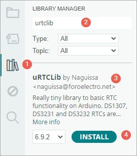
Library Installation
We’ll be using the uRTCLib library for communicating with the DS3231. This library makes reading time data from the RTC super simple.
To install the library,
- First open your Arduino IDE program. Then click on the Library Manager icon on the left sidebar.
- Type “urtclib” in the search box to filter your results.
- Look for the uRTCLib Library by Naguissa.
- Click the Install button to add it to your Arduino IDE.
Arduino Code
The sketch below communicates with the DS3231 module and shows the time on the TM1637 display in a 24-hour format.
// Include the libraries
#include <TM1637Display.h>
#include "uRTCLib.h"

// Define the connections pins
#define CLK 3
#define DIO 4

// Create rtc and display object
uRTCLib rtc(0x68);
TM1637Display display = TM1637Display(CLK, DIO);

void setup() {
  URTCLIB_WIRE.begin();

  // Comment out below line once you set the date & time.
  // Following line sets the RTC with an explicit date & time
  // for example to set April 14 2025 at 12:56 you would call:
  rtc.set(0, 56, 12, 2, 14, 4, 25);
  // rtc.set(second, minute, hour, dayOfWeek, dayOfMonth, month, year)
  // set day of week (1=Sunday, 7=Saturday)

  // Set the display brightness (0-7)
  display.setBrightness(5);

  // Clear the display
  display.clear();
}

void loop() {
  // Get the current time
  rtc.refresh();

  // Create time format to display
  int displaytime = (rtc.hour() * 100) + rtc.minute();

  // Display the current time in 24 hour format with leading zeros and a center colon enabled
  display.showNumberDecEx(displaytime, 0b01000000, true);

  delay(1000);
}
Once you upload the sketch to your Arduino, you should see:

Code Explanation
In the code, we start by including the necessary libraries: one for the TM1637 display and one for the RTC module.
#include "uRTCLib.h"We then create two objects—one for the RTC module and one for the display. The RTC object is initialized with the I2C address of the DS3231 module, which is fixed at 0x68. This address allows the Arduino to locate the module when communicating via I2C.
uRTCLib rtc(0x68);Inside the setup() function, we begin the I2C communication using URTCLIB_WIRE.begin(). This allows the Arduino to talk to the RTC module.
URTCLIB_WIRE.begin();Right after that, we set the date and time using the rtc.set() function. This function needs seven values: seconds, minutes, hours, day of the week (where 1 means Sunday), day of the month, month, and the last two digits of the year.
In our example, we’re setting the clock to 12:56 PM on Monday, April 14, 2025. That line looks like this:
rtc.set(0, 56, 12, 2, 14, 4, 25);You only need to run this line once to set the correct time. After that, you should comment it out so that the RTC keeps the time and doesn’t get reset every time you upload the code.
After setting the time, we set the brightness of the display to a medium level (5), which makes the digits clearly visible without being too bright. Then, we clear the display to ensure it starts with a blank screen.
// Set the display brightness (0-7)
display.setBrightness(5);

// Clear the display
display.clear();
In the loop() function, the first thing we do is update the time values from the RTC module using rtc.refresh(). This makes sure the latest time is loaded into the Arduino’s memory.
rtc.refresh();We then create a variable called displaytime that combines the hour and minute into a single 4-digit number. To do this, we multiply the hour by 100 and then add the minutes. For example, if the time is 09:45, the result would be 945. If it’s 14:08, the result would be 1408.
int displaytime = (rtc.hour() * 100) + rtc.minute();To actually show the time on the TM1637 display, we use the showNumberDecEx() function. We give it the 4-digit time value we just calculated, tell it to turn on the center colon (so the time looks like “14:08” instead of “1408”), and enable leading zeros so that the time always shows as four digits, like “09:05” instead of “905”.
display.showNumberDecEx(displaytime, 0b01000000, true);Finally, we add a delay(1000) so that the display updates once per second, just like a regular clock.